Electric Booster– Installation, Operating and Maintenance Instructions
5
2.4 BOOSTER HEATER LOCATION
DANGER – RISK OF EXPLOSION
Do not use or store gasoline or other flammable fuels or chemicals which have flammable vapors
near the booster. The vapors may be ignited by the heat or electronic components of the booster.
WARNING
The booster must be located in an area where water leakage of the booster or its connections will
not result in damage to the area adjacent to the appliance or to the lower floors of the structure.
When such locations cannot be avoided, a suitable drain pan must be installed under the appliance
and the drain pan must be connected to a drain of adequate capacity.
Failure to comply with the above could result in severe personal injury, death or substantial
property damage.
CAUTION
This booster must be installed such that any electronic components are protected from water
(dripping, spraying, rain, etc.) during appliance operation and service.
The space saving, compact booster heater can be installed almost
anywhere. The booster heater may be installed in an enclosed
space and attached directly to a combustible surface, however,
allow ample space for connecting, disconnecting and servicing the
unit. Locate booster heater as close to dishwasher as possible.
Dimensions are shown in Figure 1.
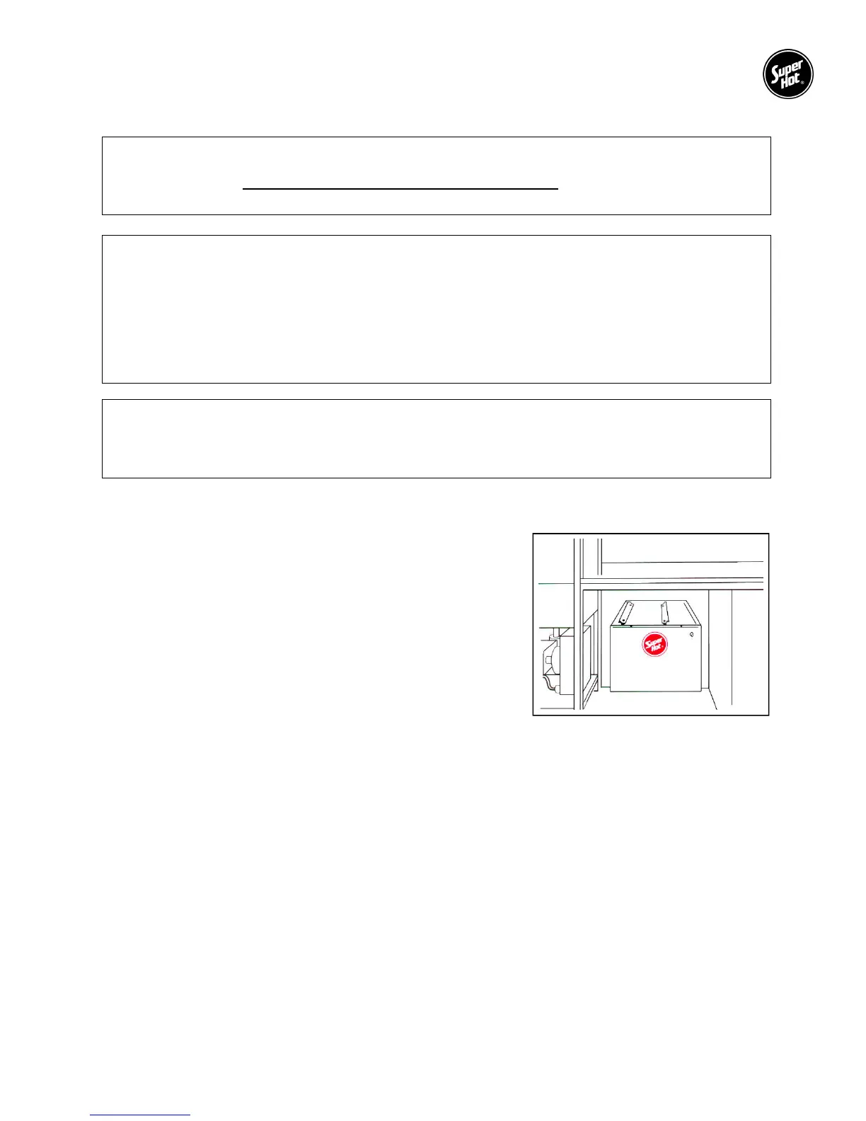
Sturdy plated steel legs are standard, but stainless steel hanging
brackets for under counter suspension are also available (specify
when ordering), see Figure 2.
2.5 PIPING
The recommended piping arrangement is shown in Figure 1. Use copper tubing only. Install the pressure
reducing valve (preset for 20 psi). Install the temperature and pressure relief valve on the booster heater
and plumb discharge in accordance with local codes. The temperature and pressure gauge attaches to a
tee on the inlet between reducing valve and booster heater. It is mandatory that a shock arrestor expansion
tank be installed on the line between booster heater and dishwasher (as close to dishwasher as possible).
It should be mounted in a vertical position above the pipe. In addition, it is recommended that the inlet and
outlet lines be insulated to prevent heat loss and that unions be used for piping connections to ease service.
All Super Hot booster heaters have 3/4" NPT inlet and outlet pipe size. Dielectric couplings should be used
in connecting dissimilar metals, such as galvanized to copper, to prevent electrolysis. A check valve should
not be installed in the supply line to the booster heater. All shut-off valves must be gate or ball valves, not
globe valves.
Figure 2 – Optional Hanging