BT Series Electric Boilers – Installation, Operating and Maintenance Instructions
5
2.4 WALL MOUNTING
CAUTION: Failure to correctly position the boiler may result in element burn out.
This boiler must be installed using the attached wall mounting brackets. It is critical that the boiler be
installed level and oriented as shown in Figure 2 (below). When correctly positioned, the front panel is
vertical and the 1 1/4”NPT outlet connection is directly above the 1 1/4”NPT inlet connection.
The wall mounting brackets on the boiler feature a “key-hole” opening suitable to fit over the head of two
previously installed 5/16” lag screws. The key-hole openings are located on 16” centers (i.e. standard
stud spacing) on the top side of the hangers. The lag screws must be suitably anchored to safely support
the weight of the boiler including water content, piping and wiring.
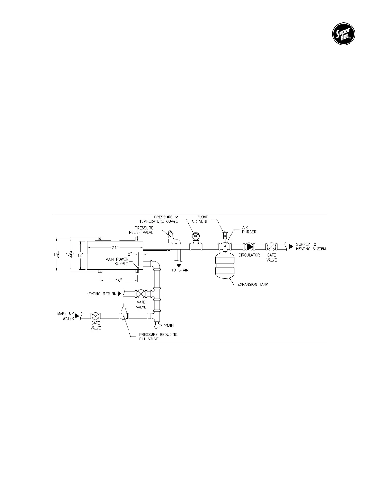
2.5 PIPING
The recommended piping arrangement is shown in Figure 2. Attach pump, expansion tank, drain valve,
pressure relief valve, air vent, pressure temperature gauge and flow switch (as required). Air vents
should be installed at points just upstream from all drops in elevation of the piping system (high points).
A boiler installed above radiation level, or as required by an authority having jurisdiction, must be
provided with a low-water cut-off device at the time of boiler installation.
Figure 2 – Piping Arrangement
 Loading...