BT Series Electric Boilers – Installation, Operating and Maintenance Instructions
6
Wiring Section 3
3.1 ELECTRICAL WIRING
All electrical wiring must be done in accordance with the Canadian Electrical Code, CSA C22.1 Part 1,
and/or any local regulations and codes in Canada, or the National Electrical code, ANSI/NFPA 70 (latest
edition) and/or any local regulations and codes in U.S.A.. Verify the nameplate rating and check the
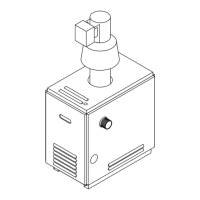
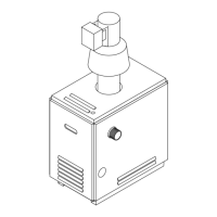
related codes to properly size conductors, switches and overcurrent protection. Several openings are
provided on the right and bottom of the casing for different voltage connections. For wire connections
refer to the wiring diagram sticker on the back of the boiler front cover.
All circuit breakers ahead of and at the boiler must be OFF. Remove the boiler front cover by removing 4
screws from the sides.
a. Wiring on Controller
Line Voltage:
Connect (if not pre-wired) only 120 Vac, 60 Hz, single phase power to terminals L1 and L2 on
the controller. Strip wire ends before inserting into terminal block. Tighten terminal screw
clamps.
Pump:
Connect only 120 Vac, 1/6 HP (maximum) pump to terminals P1 and P2 on the controller.
Strip wire ends before inserting into terminal block. Tighten terminal screw clamps. If a pump
horsepower larger than 1/6 HP is used, change the pump fuse on the controller based on the
pump rating. Do not use a pump requiring greater than 5A or 600 VA.
Thermostat:
Connect thermostat or zone valve end switch to terminals T1 and T2 (DO NOT apply any
power to these terminals!). Strip wire ends before inserting into terminal block. Tighten
terminal screw clamps.
Water Temperature Control Sensors:
Pre-wired (factory wiring) high-limit temperature sensor to terminals HL and CL (common).
Strip wire ends before inserting into terminal block. Tighten terminal screw clamps.
Pre-wired (factory wiring) operating temperature sensor to terminals OL and CL (common).
Strip wire ends before inserting into terminal block. Tighten terminal screw clamps.
b. Power Supply to Heaters
The supply cable has to be sized based on the amperage in Table 1 and the cables used.
Connect only specified line voltage and phase power to main terminal block on the control panel.
Strip wire ends before inserting into terminal block. Tighten terminal screw clamps. Attach ground
wire to ground terminal block on the bottom control panel.
NOTE: "Outdoor Reset" controllers must not be connected to the Bitronic Control System. Outdoor
Reset controllers will interfere with the Bitronic controller's normal staging routine, and lead to
excessive stage cycling and premature failure of the contactors.
 Loading...