NOTE: DIAGRAMS & ILLUSTRATIONS NOT TO SCALE.
15
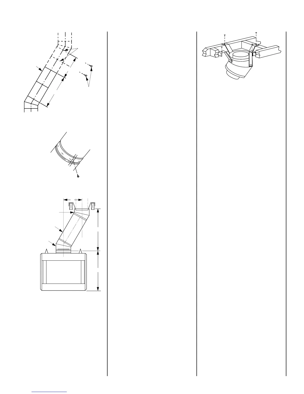
Step 1. Determine the offset distance where
chimney is to pass through the first ceiling-
dimension “A.” To find this point on your ceil-
ing, first determine the center point for a verti-
cal chimney following the instructions for ver-
tical installation.
Measure height to the ceiling from the top of
fireplace-dimension “B.” Use the appropriate
Offset Elevation Chart to find dimension “A.”
Mark point where you will drive your nail to
show the center point for your offset ceiling cut.
Step 2. Proceed by using the Straight Up Instal-
lation Instructions for cutting and framing ceil-
ing and roof openings.
Note: See Framing and Dimension Chart for the
sizes of the ceiling and roof openings. The size
of the roof opening varies with the degree of
pitch of the roof.
Offset Elbow Assembly
Offset elbows install the same as chimney
sections. First, snap the inner section INTO the
preceding inner section of flue. Check connec-
tion by pulling up slightly to ensure a tight fit.
Next, the outer sections snap lock OVER the
preceding outer section of chimney. Again,
check outer section by pulling up slightly to
ensure proper connection is made.
Return Elbow Assembly
Return elbows install the same way as round
terminations and stabilizers:
Step 1. Hold return elbow over top of last
chimney section.
Step 2. Center inner slip section into inner flue
pipe-slip down.
Step 3. Center outer-locking section over outer
chimney pipe. Push down until locking joint has
firmly engaged.
Step 4. Pull up slightly on return elbow to
ensure locking joint has firmly engaged.
Step 5. Secure support straps to framing
members by nailing under tension in sheer
(
Figure 40
).
Note: The return elbow assembly performs the
same function as a stabilizer. Consider this
when determining the need for a stabilizer.
Figure 37
Figure 38
Figure 39
Chimney
Section
Joints
No. 8 x 1/2" SMS
Screws Required At
Every Joint Past 6'
No Screws Required In
Joints For First 6' of Offset
4'
6'
Underside Of Chimney
Return
Elbow
Figure 40
Note: Do not apply excessive pressure to any
subsequent chimney section following return
elbow assembly when installing. Ensure that
each subsequent chimney section is securely
attached by testing as noted above.
OPTIONAL EQUIPMENT
CONSIDERATIONS
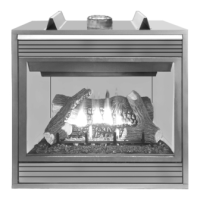
Forced Air Kits – BCF Series Only
If you are installing a forced air kit, Model
FAK-1500, on BCF models; see the installa-
tion instructions provided with the kit for
electrical wiring requirements. Use a fan
adapter kit, Model CF-ADK, to allow the fire-
place to be connected to the main power
supply. The fireplace must be connected to
main power supply at time of installation if a
forced air kit is to be installed later. The
electrical connections must be made before
the fireplace is framed and enclosed in the
finished walls.
CAUTION: ELECTRICAL CONNECTIONS
SHOULD ONLY BE PERFORMED BY A QUALI-
FIED, LICENSED ELECTRICIAN. MAIN POWER
MUST BE OFF WHEN CONNECTING THE CF-
ADK ADAPTER TO MAIN ELECTRICAL POWER
SUPPLY OR PERFORMING SERVICE.
Variable Speed Wall Switch
Refer to the installation instructions provided
with the variable speed wall switch, Model
VSWS, for installation details.
Combustion Air Kits
Use combustion air kit, Model AK-4 or AK4-LD,
with the BCF and BRF Series fireplaces. Refer to
installation instructions packed with the air kits
for specific installation information. The out-
side air kit must be installed before the fireplace
is framed and enclosed in the finished walls.
B
-30 Offset Elbow*
-E30 Return Elbow
Chimney Section(s)
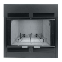
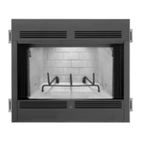
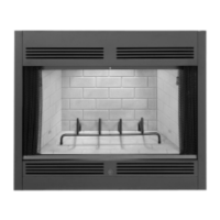
43" Fireplace With FTF10 Chimney System
38" Fireplace With FTF8 Chimney System
A
38"
*Part of Offset/Return Package,
Models FTF8-ES30, FTF10-ES30
INSTALLING OFFSETS
First, review the appropriate Offset Elevation
Chart and
Figure 39
for reference.