NOTE: DIAGRAMS & ILLUSTRATIONS NOT TO SCALE.
6
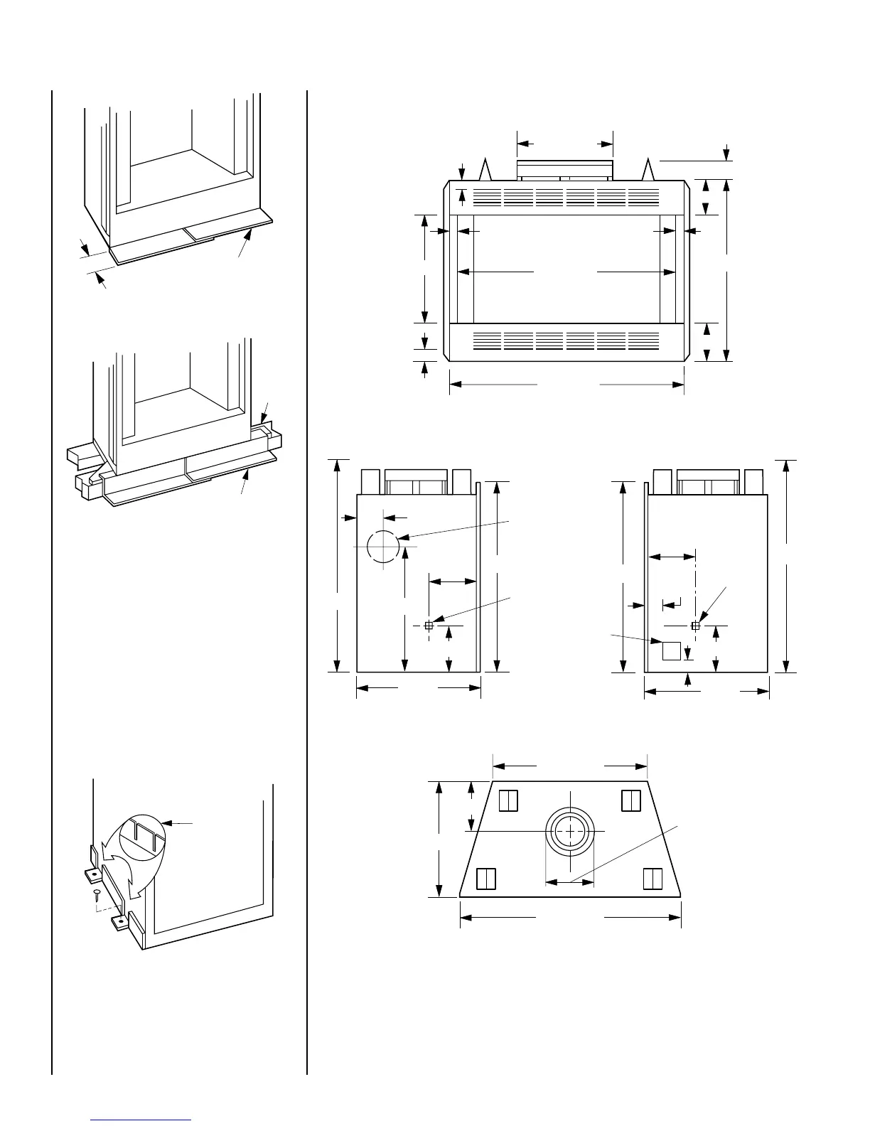
FIREPLACE SPECIFICATIONS
Figure 11
Metal Safety Strips
1 ¹⁄₂"
IMPORTANT: UNDER NO CIRCUMSTANCES
CAN THE FIREPLACE TOP SPACERS BE RE-
MOVED OR MODIFIED, NOR MAY YOU NOTCH
THE HEADER TO FIT AROUND OR BE IN-
STALLED LOWER THAN THE SPACERS. THE
HEADER MAY BE IN DIRECT CONTACT WITH
THE TOP SPACERS BUT MAY NOT BE SUP-
PORTED BY THEM.
Step 4. Fireplace may be anchored to floor.
Bend down four (4) anchor tabs located at the
base of the fireplace and secure to the floor by
nailing with 8d nails (
Figure 10
).
Figure 10
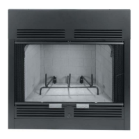
Figure 8
Figure 9
Blocking
Metal Safety Strips
Anchor Tab
38 = 40 5/8"
43 = 45 3/8"
6 1/2"
34 1/2"
7"
21"
38 = 38"
43 = 42 3/4"
1 5/16" 1 5/16"
1 1/2"
2 1/4"
4 1/4"
38 = 12 1/2"
43 = 15"
34 1/2"
Gas Line
Knockout
4 1/2"
8 1/4"
38 3/4"
Combustion
Air Inlet
8 1/2"
21 1/2"
23"
34 1/2"
Gas Line
Knockout
8 1/4"
38 3/4"
8 1/2"
21 1/2"
J Box
Cover
3"
3 1/2"
38 = 40 5/8"
43 = 45 3/8"
38 = 12 1/2"
43 = 15"
21 1/2"
38 = 29 1/8"
43 = 33 3/4"
9"
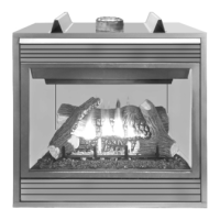
BCF Model Shown
Left Side Right Side
Top