General Information
900004-00, 03/2017
Innovative Hearth Products
DRT2000 and DRC2000 Direct-Vent Fireplaces
12
VENT TERMINATION CLEARANCES
These instructions should be used as a guideline and do not supersede local codes in any way. Install venting
according to local codes, these instructions, the current National Fuel Gas Code (ANSI Z223.1/NFPA 54) in the USA or
the current standards of CAN/CGA-B149.1 in Canada.
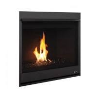
Vertical Vent Termination Clearances
Terminate multiple vent terminations according to the installation codes listed above and Figure 4.
Figure 4 - Multiple Terminations
Terminate single vent caps relative to building components according to Table 6 and Figure 4.
Roof Pitch Termination Height *
Flat to 6/12 1.0 ft (0.3 m)
6/12 to 7/12 1.25 ft (0.38 m)
7/12 to 8/12 1.5 ft (0.46 m)
8/12 to 9/12 2.0 ft (0.61 m)
9/12 to 10/12 2.5 ft (0.76 m)
10/12 to 11/12 3.25 ft (0.99 m)
11/12 to 12/12 4.0 ft (1.22 m)
12/12 to 14/12 5.0 ft (1.52 m)
14/12 to 16/12 6.0 ft (1.83 m)
16/12 to 18/12 7.0 ft (2.13 m)
18/12 to 20/12 7.5 ft (2.29 m)
20/12 to 21/12 8.0 ft (2.44 m)
12
X
Roof pitch is X/12
2 ft
minimum
2 ft minimum
Lowest
discharge
opening
H*
*H = minimum height from roof to
lowest discharge opening of vent
Horizontal overhang
Vertical
wall
Vent
termination
Storm collar
Concentric
vent pipe
Flashing
1” (25.4 mm) minimum
clearance to combustibles
Table 6 - Termination Heights for Vents above Flat or Sloped Roofs (NFPA 54 / ANSI Z223.1)—Gas Vent Rule
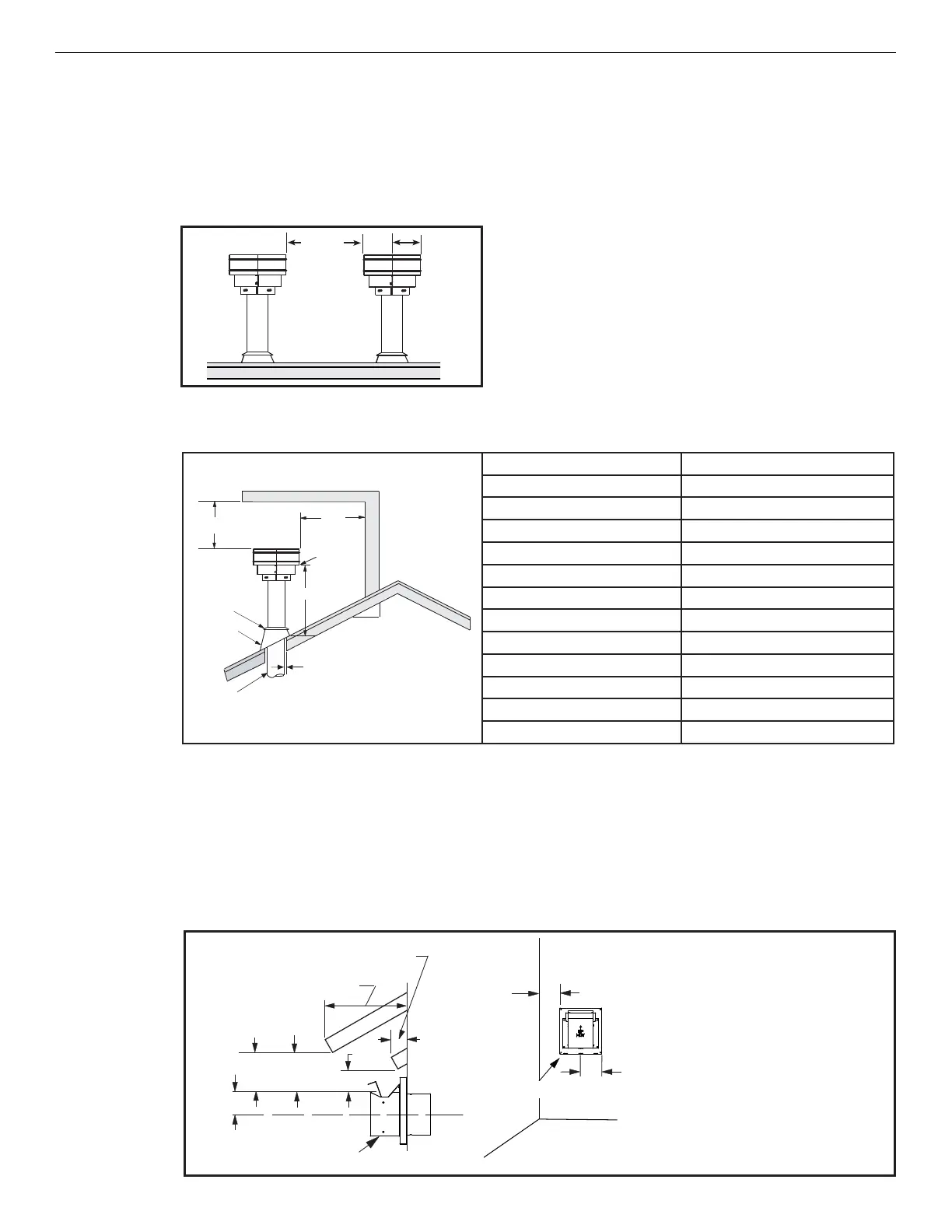
Horizontal Vent Termination Clearances
The horizontal vent termination must have a minimum of 6” (152 mm) clearance to any overhead combustible
projection of 2-1/2” (64 mm) or less (Figure 5). For projections exceeding 2-1/2” (64 mm) (Figure 5). For additional
vent location restrictions refer to Table 7.
All horizontal terminations may be located as close as 6” (152mm) to any (non-combustible and combustible)
exterior sidewall. This distance may be decreased to 2” (51mm) for noncombustible exterior sidewalls with all
approved terminations (Table 7).
Figure 5 - Horizontal Vent Termination Clearances
NOTE: See Figure 28
on Page 31 for exterior
wall recess allowances
for compact horizontal
termination.
12”
(305 mm)
minimum
6”
(153 mm)
Termination kit*
6”
Use 6-1/2” for
all horzontal
terminations
applicable
*4” to center of termination for F1797, 8” for 94L10, and 10” for H1968
Combustible projection 2
1/2” or less in length
Combustible projection
greater than 2-1/2” in length
Ventilated
soffi t - 18”
(457 mm)
Unventilated
soffi t - 12”
(305 mm)
6
(152)
Termination kit
*