12
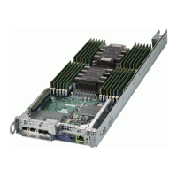
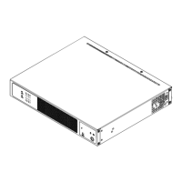
SuperServer E300-9A-4CN10P User's Manual
Quick Reference Table
Jumper Description Default Setting
JBR1 BIOS Recovery Pins 1-2 (Normal)
JBT1 CMOS Clear Open (Normal)
JI
2
C1, JI
2
C2 SMB to PCI-E Slots Enable/Disable Pins 2-3 (Disabled)
JPG1 Onboard VGA Enable/Disable Pins 1-2 (Enabled)
JPL1 LAN1 SFP Port Enable/Disable Pins 1-2 (Enabled)
JPL2 LAN2 SFP Port Enable/Disable Pins 1-2 (Enabled)
JPL3 LAN3-6 Ports Enable/Disable Pins 1-2 (Enabled)
JPL4 LAN7-10 Ports Enable/Disable Pins 1-2 (Enabled)
JPME2 ME Manufacturing Mode Pins 1-2 (Normal)
JSEL1 PCI-E Slot 6/7 Selection Pins 1-2: Slot 7
JWD1 Watch Dog Timer Pins 1-2 (Reset)
LED Description Status
LED1 Power LED Solid Green: Power On
LEDM1 BMC Heartbeat Blinking Green: BMC Normal
UIDLED1 UID LED
Connector Description
BT1 Onboard Battery
COM1 COM Header
FAN1 - FAN3, FANA, FANB CPU/System Fan Headers
IPMI LAN IPMI LAN Port
I-SATA0-4 SATA 3.0 Ports
SATA1/2 are disabled when Slot6/Slot7 selected as PCI-E 3.0 x2 in the BIOS
JD1 Speaker (Pins 1-4)
JF1 Front Control Panel Header
JFPCLED1 LED Board Cable Connector for FPB-FPE300-LED10
JGP1 General Purpose I/O Header
JIPMB1 System Management Bus Header (for IPMI card)
JL1 Chassis Intrusion Header
JLANLED1 LAN3-6 Active LED
JLANLED2 LAN7-8 Active LED
JLANLED3 LAN9-10 Active LED
JMD1 M.2 B-Key PCI-E3.0/SATA3.0/USB3.0 Slot
 Loading...