33
Chapter 3 Motherboard Connections
COM Header
The motherboard has one COM header for front access to provide a serial connection.
COM Header
Pin Denitions
Pin# Denition Pin# Denition
1 DCD 6 DSR
2 RXD 7 RTS
3 TXD 8 CTS
4 DTR 9 RI
5 Ground 10 N/A
Universal Serial Bus (USB) Ports
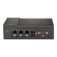
There are three USB 3.1 Gen 1 Type-A (USB0/1 rear and USB4 header) and one USB 2.0
header (USB2/3). The onboard header can be used to provide front side USB access with a
cable (not included). USB 3.1 Gen 1 is also referred to as USB 3.0
Type A USB 3.1 Gen 1
Pin Denitions
Pin# Denition
1 VBUS
2 D-
3 D+
4 Ground
5 StdA_SSRX-
6 StdA_SSRX+
7 GND_DRAIN
8 StdA_SSTX-
9 StdA_SSTX+
UID Button
Pin Denitions
Pin# Denition
1 Ground
2 Ground
3 Button In
4 Button In
UID LED
Pin Denitions
Color Status
Blue: On
Unit Identier Button/UID LED Indicator
button (JUIDB) is located next to the VGA port on the back panel. The UID LED is located at
UIDLED1, next to the UID button. When you press the UID button, the UID LED will be turned
Note: UID can also be triggered via IPMI on the motherboard. For more information
on IPMI, please refer to the IPMI User's Guide posted on our website at https://www.
supermicro.com/support/manuals/.
USB 2.0 Header (USB2/3)
Pin Denitions
Pin# Denition Pin# Denition
1 +5V 6 +5V
2 USB_N 7 USB_N
3 USB_P 8 USB_P
4 Ground 9 Ground
5 Key 10 NC
 Loading...

