34
SuperServer E300-9D-4CN8TP/E300-9D-8CN8TP User's Manual
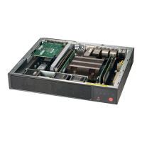
3.4 Front Control Panel
JF1 contains header pins for various buttons and indicators that are normally located on a
buttons and LED indicators.
Power Button
OH/Fan Fail LED
NIC1 Activity LED
Reset Button
HDD LED
PWR LED
Reset
PWR
3.3V Stby
3.3V Stby
Ground
15
3.3V Stby
16
1 2
Ground
NIC2 Activity LED
PWR Fail LED
UID
3.3V
3.3V
Figure 3-2. JF1: Control Panel Pins
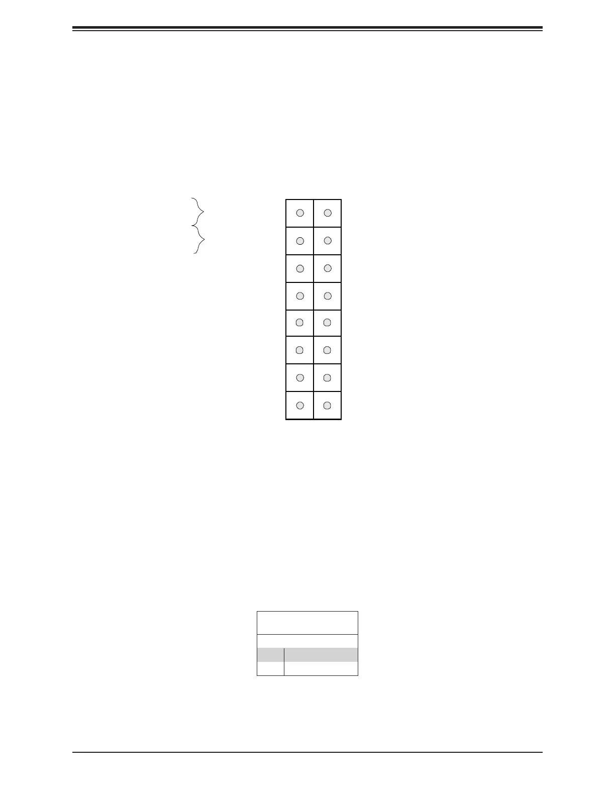
Power Button
The Power Button connection is located on pins 1 and 2 of JF1. Momentarily contacting both
is in suspend mode, press the button for 4 seconds or longer. Refer to the table below for
Power Button
Pin Denitions (JF1)
Pin# Denition
1 Signal
2 Ground