1-6
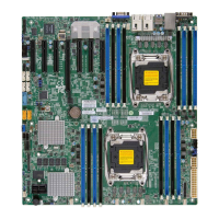
X10DRi/X10DRi-T Motherboard User’s Manual
Warning!
To avoid damaging the power supply or the motherboard, be sure to use a power
supply that contains a 24-pin and two 8-pin power connectors. Be sure to connect the
power supply to the 24-pin power connector (J24), and two 8-pin power connectors
(JPWR1, JPWR2) on the motherboard. Failure in doing so may void the manufacturer
warranty on your power supply and motherboard.
(CPU2) Slot4 PCI-Express 3.0 x16 Slot from CPU2
(CPU2)Slot5 PCI-Express 3.0 x8 Slot from CPU2
(CPU1)Slot6 PCI-Express 3.0 x16 Slot from CPU2
(T-)SGPIO1/2/3 Seria_Link General Purpose I/O Headers 1/2/3 (for SATA
ports), (T-SGPIO1 for I-SATA0-3, T-SGPIO2 for I-SATA4/5, T-
SGPIO3 for S-SATA0-3)
SP1 Internal Speaker/Buzzer
(BP) USB 0/1 Backpanel USB 2.0 Ports 0/1
(BP) USB 6/7 Backpanel USB 3.0 Ports 6/7
(FP) USB 2/3, 4/5 Front Accessible USB 2.0 Connection Headers 2/3 (J25), 4/5
(J27)
(FP) USB 10 Front Panel Accessible Type A 3.0 Connector USB10 (J26)
(FP) USB 8/9 Front Panel Accessible Vertical USB 3.0 Connector for USB
8/9 (J-USB3-1AA)
VGA Backpanel VGA Port
X10DRi/X10DRi-T LED Indicators
LED Description State Status
LE1 Rear UID LED Blue: On Unit Identied
LE2 Onboard PWR LED On System Power On
LEDM1 BMC Heartbeat LED Green: Blinking BMC Normal

 Loading...

