Do you have a question about the Supermicro X10DAL-i and is the answer not in the manual?
Provides an overview of the Super X10DAL-i motherboard's features and capabilities.
Outlines the structure of the user manual, detailing chapter contents.
Lists the items typically included in the retail box with the motherboard for verification.
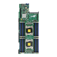
Illustrates the physical layout of the motherboard, identifying key components and connectors.
Provides a visual quick reference for motherboard jumpers, I/O ports, and front panel connections.
Details the function and default settings of various jumpers on the motherboard for configuration.
Lists and describes the various connectors available on the motherboard for system integration.
Summarizes the key technical features of the motherboard, including CPU, memory, chipset, and expansion slots.
Details the motherboard's support for peripheral devices, including USB, I/O, power, BIOS, and Thunderbolt technology.
Explains the motherboard's capabilities for monitoring system health, including CPU, fan, and temperature.
Presents a block diagram illustrating the internal architecture and connectivity of the motherboard.
Provides an overview of the supported Intel processors and the C612 chipset functionality.
Highlights special features such as AC power loss recovery and system health monitoring functions.
Describes the Advanced Configuration and Power Interface (ACPI) features for power management.
Specifies the power supply requirements and recommendations for system stability and operation.
Explains the functions of the Super I/O chip for serial communication and power management.
Presents industry-standard warnings to ensure user safety during installation procedures.
Provides instructions and warnings regarding the proper disposal of the product according to regulations.
Details precautions and procedures to protect components from electrostatic discharge (ESD) during handling.
Guides users through the process of physically installing the motherboard into a computer chassis.
Covers the critical steps for installing the CPU and its associated heatsink securely.
Provides detailed, step-by-step instructions for correctly installing the LGA2011 processor into the socket.
Explains the procedure for mounting a passive CPU heatsink onto the processor for cooling.
Details the process and precautions for removing the CPU heatsink to avoid damage.
Instructs on how to properly install and remove RAM modules from the motherboard slots.
Explains the configuration options and compatibility for RDIMM and LRDIMM ECC memory modules.
Identifies and describes the various connectors and ports located on the motherboard's I/O panel.
Details the dual Gigabit Ethernet ports, including their pin definitions and LED indicators.
Describes the USB ports and headers, providing pin definitions for different USB standards.
Explains the onboard audio features and provides pin definitions for audio headers and rear connections.
Details the front panel connectors, including buttons and LEDs, and their pin assignments.
Provides specific pin definitions for the NMI Button and Power LED on the front control panel header.
Explains the pin definitions for HDD and Network Interface Card (NIC) LEDs for status indication.
Details the pin assignments for Overheat/Fan Fail and Power Fail LEDs for system status alerts.
Provides pin definitions for the system Reset Button and Power Button connections.
Guides on connecting essential power cables to the motherboard for system operation.
Explains the pin definitions for fan headers and the chassis intrusion detection header.
Details pin configurations for the internal speaker (buzzer) and power LED/speaker connections.
Describes the pin definitions for TPM/Port 80 headers and the standby power header.
Details pin configurations for SGPIO headers and SATA DOM power connectors.
Explains pin definitions for SPDIF audio headers and the Power SMB (I2C) connector.
Identifies the location and purpose of the COM header for serial port connectivity.
Covers the explanation of jumpers and specific settings for system configuration.
Details jumper settings for clearing CMOS and enabling/disabling the Watch Dog timer.
Explains jumper settings for I2C bus to PCI-E slots and manufacturer mode selection.
Describes the jumper setting to enable or disable the onboard audio functionality.
Details the jumper setting for enabling USB wake-up functionality from specific ports.
Explains the onboard LEDs, including LAN and power LEDs, and their status indications.
Describes the SATA 3.0 ports, their support for SuperDOMs, and pin definitions.
Provides systematic steps to diagnose and resolve common system issues.
Initial checks and procedures to perform before attempting to power on the system.
Steps to diagnose and resolve issues where the system does not power on.
Troubleshooting steps for when the system powers on but displays no video output.
Procedures for diagnosing and fixing problems that prevent the system from booting correctly.
Addresses issues related to the system losing its BIOS setup configuration settings.
Guides on identifying and resolving issues related to memory module detection and functionality.
Offers steps to diagnose and fix system instability problems occurring during or after OS installation.
Outlines the recommended steps to take before contacting technical support for assistance.
Provides instructions for safely removing, disposing of, and installing the onboard CMOS battery.
Addresses common user questions regarding memory support and BIOS updates.
Explains the procedure for returning the product for warranty service or repairs.
Lists and explains the beep codes generated during the Power-On Self-Test (POST) for error identification.
Details the process of installing essential software programs and drivers after the operating system is set up.
Explains how to configure SuperDoctor 5, a hardware monitoring and management utility.
Provides a general explanation of the Unified Extensible Firmware Interface (UEFI) and its role.
Describes the structure of the UEFI BIOS image and the process for recovering a corrupted BIOS.
Offers step-by-step instructions for performing UEFI BIOS recovery using a USB-attached storage device.
| Form Factor | ATX |
|---|---|
| Chipset | Intel C612 |
| Memory Slots | 8 |
| Maximum Memory | 512GB |
| PCI 32-bit | 1 |
| RAID Support | 0, 1, 5, 10 |
| USB 3.0 Ports (Rear) | 4 |
| USB 3.0 (Header) | 2 |
| USB 2.0 Ports (Rear) | 4 |
| USB 2.0 (Header) | 2 |
| PCIe 3.0 x8 Slots | 1 |
| PCIe 2.0 x4 Slots | 0 |
| SATA 3Gb/s | 0 |
| SAS | 0 |
| LAN Ports | 2 |
| Power Connector | 24-pin ATX |
| Memory Type | DDR4 |
| PCIe 3.0 x16 Slots | 3 |