1-6
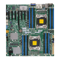
X10DAL-i Motherboard User's Manual
Warning: To prevent damage to the power supply or motherboard, please use a power
supply that contains a 24-pin and two 8-pin power connectors. Be sure to connect
these power supply connectors to the 24-pin power connector (J24) and two 8-pin
power connectors (JPWR1, JPWR2) on the motherboard. Failure in doing so will void
the manufacturer warranty on your power supply and motherboard.
JSTBY1 Standby power header
JTBT1 GPIO (General-Purpose I/O) header for Thunderbolt add-on card (See
the note on page 1-5 for Thunderbolt AOC support.)
JTPM1 TPM (Trusted Platform Module)/Port 80 header
LAN1/LAN2 Gigabit Ethernet ports 1/2
I-SATA0-5 Serial_Link ATA (SATA 3.0) connections 0-5 supported by Intel PCH
(I-SATA4/5 support Supermicro SuperDOMs [Devices-on-Module] with
power pins built-in)
S-SATA 0-3 Serial_Link ATA (SATA 3.0) connections 0-3 supported by Intel SCU
SP1 Onboard buzzer (internal speaker)
I-SGPIO 1/2, S-SGPIO Serial_Link General_Purpose IO (SGPIO) headers (I-SGPIO 1: I-SA-
TA0-3, I-SGPIO 2: I-SATA4/5, S-GPIO: S-SATA0-3)
USB 3/4 (3.0) Rear USB 3.0 ports 3/4 on the IO backpanel
USB 1/2 (2.0) Front USB 2.0 ports 1/2 for front access
USB 5/6 (3.0) Rear USB 3.0 ports 5/6 on the IO backpanel
USB 7/8 (3.0) Front-accessible USB 3.0 connections 7/8
USB 0 (2.0) Type A USB 2.0 USB connection header
X10DAL-i LED Indicators
LED Description State
LEDPWR Power LED Solid On: Power On, Blinking: Suspend to RAM
 Loading...


