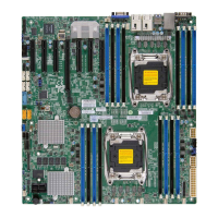
2-24
X10DAL-i Motherboard User's Manual
Power Button
OH/Fan Fail LED
1
NIC1 LED
Reset Button
2
HDD LED
Power LED
Reset
PWR
Vcc
Vcc
Vcc
Vcc
Ground
Ground
1920
Vcc
X
Ground
NMI
X
Vcc
PWR Fail LED
NIC2 LED
Power Button
The Power Button connection is located
on pins 1 and 2 of JF1. Momentarily
contacting both pins will power on/off the
system. Refer to the table on the right for
pin denitions.
Power Button
Pin Denitions (JF1)
Pin # Denition
1 Signal
2 Ground
Reset Button
The Reset Button connection is located
on pins 3 and 4 of JF1. Attach it to a
hardware reset switch on the computer
case. Refer to the table on the right for
pin denitions.
Reset Button
Pin Denitions (JF1)
Pin # Denition
3 Reset
4 Ground
A. Reset Button
B. PWR Button
A
B
BT1
JPCIE3
LEDPWR
I-SGPIO2
LE6
JBT1
BIOS
LICENSE
JPI2C1
JTBT1
J24
JPWR1
JPWR2
JF1
JD1
JHD_AC1
JSPDIF_OUT
JSPDIF_IN
J21
JL1
JSD1
JSD2
JSTBY1
JTPM1
JVRM2
JVRM1
JPAC1
JPL2
JPL1
JPUSB1
JBR1
JI2C2
JPME2
JI2C1
J23
SP1
FAN3
FANA
FAN6
FAN4
FAN2
FAN1
MAC CODE
X10DAL-i
BAR CODE
AUDIO FP
HD AUDIO
(3.0)
USB5/6
(3.0)
USB7/8(3.0)
USB1/2
USB0
USB3/4
S-SATA2
S-SATA0
S-SATA1
S-SATA3
I-SATA5
CPU1 SLOT1 PCI-E 3.0 X8 (IN X16)
I-SATA4
CPU2 SLOT2 PCI-E 3.0 X4 (IN X8)
I-SATA3
I-SATA2
I-SATA1
CPU1 SLOT3 PCI-E 3.0 X16
I-SATA0
CPU1 SLOT5 PCI-E 3.0 X16
P2-DIMME1
P1-DIMMC1
P2-DIMMF1
P1-DIMMD1
P2-DIMMH1
P1-DIMMB1
P1-DIMMA1
LAN2
P2-DIMMG1
LAN1
COM1
I-SGPIO1
S-SGPIO
PCH SLOT6 PCI-E 2.0 X4 (IN X8)
JWD1
Rev. 1.02
1
FAN5
CPU1
CPU2
Battery
PCH
BIOS
 Loading...


