10
Super X11SCE-F User's Manual
J25
BMC_HB_LED1
A
C
JTPM1
BT1
+
JBT1
LED5
A
C
I-SATA6
JSD1
SW2
J22
JKVM1:
JPME2
JPG1
JPME1
JBR1
SRW3
SRW4
BIOS
LICENSE
MAC CODE
DESIGNED IN USA
X11SCE-F
REV:1.02
USB0/1
UID
CPU MICRO-LP PCIE 3.0 X8
DIMMB2
DIMMA2
DIMMB1
DIMMA1
VGA
CPU
JSD1:SATA DOM POWER
BAR CODE
JWD1
I-SATA0
LED1
A
C
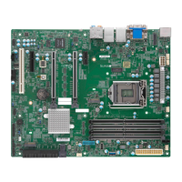
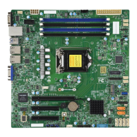
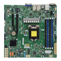
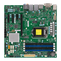
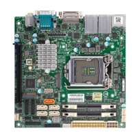
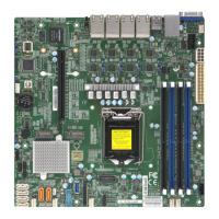
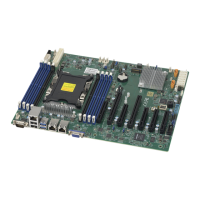
Figure 1-2. X11SCE-F Motherboard Layout
(not drawn to scale)
Notes:
• See Chapter 2 for detailed information on jumpers and I/O ports. Jumpers/components/
LED indicators not indicated are used for internal testing only.
• " " indicates the location of Pin 1.
• Use only the correct type of onboard CMOS battery as specied by the manufacturer. Do
not install the onboard battery upside down to avoid possible explosion.
LED5
MICRO-LP
SW2
LED1
BMC_HB_LED1
JTPM1
I-SATA0
DIMMB1
DIMMA1
DIMMA2
DIMMB2
JKVM1
JPME1
JBR1
J25
I-SATA6
UID
JPG1
JPME2
JSD1
JBT1
SRW4
SRW3
J22
BT1
Top View Bottom View
JWD1
 Loading...
