33
Chapter 2: Installation
I-SATA0
LED1
A
C
J25
BMC_HB_LED1
A
C
JTPM1
BT1
+
JBT1
LED5
A
C
I-SATA6
JSD1
SW2
J22
JKVM1:
JPME2
JPG1
JPME1
JBR1
SRW3
SRW4
BIOS
LICENSE
MAC CODE
DESIGNED IN USA
X11SCE-F
REV:1.02
USB0/1
UID
CPU MICRO-LP PCIE 3.0 X8
DIMMB2
DIMMA2
DIMMB1
DIMMA1
VGA
CPU
JSD1:SATA DOM POWER
BAR CODE
JWD1
I-SATA 3.0 Ports
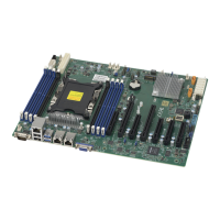
The X11SCE-F has two I-SATA 3.0 ports via the backplane (I-SATA0), one via the right angle
receptor connector. These SATA ports are supported by the C246 chipset. I-SATA6 can be
used with Supermicro SuperDOMs that are yellow SATA DOM connectors with power pins
built in, and do not require external power cables. Supermicro SuperDOMs are backward-
compatible with regular SATA HDDs or SATA DOMs that need external power cables.
2
1. I-SATA0
2. I-SATA6
3. M.2 Slot
3
1
M.2 Slots
There is one M.2 slot at J25. M.2 is formerly known as Next Generation Form Factor (NGFF).
They are designed for internal mounting devices and provide M Key 2280//22110 support
dedicated for SSD devices.
Top View Bottom View
 Loading...
