45
Chapter 2: Installation
+
+
SAN MAC
IPMI CODE
BIOS LICENSE
DESIGNED IN USA
MAC CODE
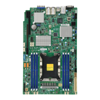
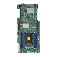
X11SPG-TF
REV: 1.01
BAR CODE
JPWR6
JUIDB1
JPWR5
JL1
JOH1
JPME2
JWD1
JPG1
JP1
JPTG1
JPCK1
LE1
LE3
LEDM1
LE2
LE4
FAND
FAN1
FAN2
FAN4
FAN3
FANA
FANC
S-SGPIO1
I-SGPIO2
JP3
JP2
JBT1
MH12
MH10
JTPM1
JSD2
JSD1
JIPMB1
JNVI2C1
JRK1
JSTBY1
BT1
SP1
JD1
I-SATA7
I-SATA6
I-SATA5
I-SATA4
S-SATA1
S-SATA0
JF1
JP4
SXB2A
SXB1A
M.2-H_2 PCI-E 3.0 X4
SXB1B PCI-E 3.0 X16
CPU SLOT3 PCI-E 3.0 X16
SXB2B PCI-E 3.0 X16
M.2-H_1 PCI-E 3.0 X4
USB4/5(3.0)
USB6/7(3.0)
USB8(3.0)
USB2/3
COM2
LAN2
VGA
CPU
LAN1
DIMMB1
LEDLED12LEDFAIL
ON
DIMMA1
NMIXPWRHDDNICNICUIDPSRSTPWR
DIMMF1
DIMME1
DIMMD1
DIMMC1
IPMI_LAN
Aspeed
AST2500
Intel
C621
Intel
X550
2.7 Connectors
Power Connections
Required Connection
1
Main Power 20-pin Connector
Pin Denitions
Pin# Denition Pin# Denition
11 PS_ON_N 1 GND
12 P5V_STBY 2 GND
13 GND 3 GND
14 GND 4 GND
15 GND 5 GND
16 NC 6 NC
17 P12V 7 P12V
18 P12V 8 P12V
19 P12V 9 P12V
20 P12V 10 P12V
8-pin Power
Pin Denitions
Pin# Denition
1 - 4 GND
5 - 8 P12V (12V Power)
1. 20-Pin Main PWR
2. 8-Pin GPU PWR
Main Power and GPU Power Connectors
The 20-pin main power connector (JPWR5) is used to provide power to the motherboard,
while the 8-pin GPU power connector (JPWR6) can be connected to power the GPU card.
These power connectors meet the SSI EPS 12V specication. See the tables below for pin
denitions.
2
 Loading...
