50
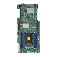
Super X11SPG-TF User's Manual
+
+
SAN MAC
IPMI CODE
BIOS LICENSE
DESIGNED IN USA
MAC CODE
X11SPG-TF
REV: 1.01
BAR CODE
JPWR6
JUIDB1
JPWR5
JL1
JOH1
JPME2
JWD1
JPG1
JP1
JPTG1
JPCK1
LE1
LE3
LEDM1
LE2
LE4
FAND
FAN1
FAN2
FAN4
FAN3
FANA
FANC
FANB
S-SGPIO1
I-SGPIO2
JP3
JP2
JBT1
MH12
MH10
JTPM1
JSD2
JSD1
JIPMB1
JNVI2C1
JRK1
JSTBY1
BT1
SP1
JD1
I-SATA7
I-SATA6
I-SATA5
I-SATA4
S-SATA1
S-SATA0
JF1
JP4
SXB2A
SXB1A
M.2-H_2 PCI-E 3.0 X4
SXB1B PCI-E 3.0 X16
CPU SLOT3 PCI-E 3.0 X16
SXB2B PCI-E 3.0 X16
USB1
M.2-H_1 PCI-E 3.0 X4
USB4/5(3.0)
USB6/7(3.0)
USB8(3.0)
USB2/3
COM2
LAN2
VGA
CPU
LAN1
DIMMB1
LEDLED12LEDFAIL
ON
DIMMA1
NMIXPWRHDDNICNICUIDPSRSTPWR
DIMMF1
DIMME1
DIMMD1
DIMMC1
IPMI_LAN
USB0
Aspeed
AST2500
Intel
C621
Intel
X550
Standby Power
The Standby Power header is located at JSTBY1 on the motherboard. You must have a card
with a Standby Power connector and a cable to use this feature. Refer to the table below
for pin denitions.
Standby Power
Pin Denitions
Pin# Denition
1 +5V Standby
2 GND
3 No Connection
Internal Speaker/Buzzer
The Internal Speaker/Buzzer (SP1) is used to provide audible indications for various beep
codes. Refer to the table below for pin denitions.
Internal Buzzer
Pin Denitions
Pin# Denition
1 Pos (+) Beep In
2 Neg (-) Alarm Speaker
2
1. Standby Power
2. Internal Speaker
1
 Loading...
