53
Chapter 2: Installation
Power LED/Speaker
Pins 1-3 of JD1 are used for power LED indication, and pins 4-7 are for the speaker. Please
note that the speaker connector pins (4-7) are used with an external speaker. If you wish to
use the onboard speaker, you should close pins 6-7 with a cap. Refer to the tables below
for pin denitions.
PWR LED Connector
Pin Denitions
Pin# Signal
1 JD1_PIN1
2 FP_PWR_LED
3 FP_PWR_LED
Speaker Connector
Pin Denitions
Pin# Signal
4 P5V
5 Key
6 R_SPKPIN_N
7 R_SPKPIN
+
+
SAN MAC
IPMI CODE
BIOS LICENSE
DESIGNED IN USA
MAC CODE
X11SPG-TF
REV: 1.01
BAR CODE
JPWR6
JUIDB1
JPWR5
JL1
JOH1
JPME2
JWD1
JPG1
JP1
JPTG1
JPCK1
LE1
LE3
LEDM1
LE2
LE4
FAND
FAN1
FAN2
FAN4
FAN3
FANA
FANC
FANB
S-SGPIO1
I-SGPIO2
JP3
JP2
JBT1
MH12
MH10
JTPM1
JSD2
JSD1
JIPMB1
JNVI2C1
JRK1
JSTBY1
BT1
SP1
JD1
I-SATA7
I-SATA6
I-SATA5
I-SATA4
S-SATA1
S-SATA0
JF1
JP4
SXB2A
SXB1A
M.2-H_2 PCI-E 3.0 X4
SXB1B PCI-E 3.0 X16
CPU SLOT3 PCI-E 3.0 X16
SXB2B PCI-E 3.0 X16
USB1
M.2-H_1 PCI-E 3.0 X4
USB4/5(3.0)
USB6/7(3.0)
USB8(3.0)
USB2/3
COM2
LAN2
VGA
CPU
LAN1
DIMMB1
LEDLED12LEDFAIL
ON
DIMMA1
NMIXPWRHDDNICNICUIDPSRSTPWR
DIMMF1
DIMME1
DIMMD1
DIMMC1
IPMI_LAN
USB0
Aspeed
AST2500
Intel
C621
Intel
X550
1. Speaker Header
2. Dual M.2 Slots
1
M.2 Slot
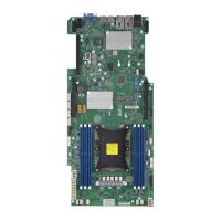
The X11SPG-TF motherboard has two M.2 slots. M.2 was formerly known as Next Generation
Form Factor (NGFF) and serves to replace mini PCI-E. M.2 allows for a variety of card sizes,
increased functionality, and spatial eciency. The M.2 socket on the motherboard supports
PCI-E 3.0 x4 (32 Gb/s) SSD cards in the 2280 and 22110 form factors. It can also support
SATA devices.
2
 Loading...
