49
Chapter 2: Installation
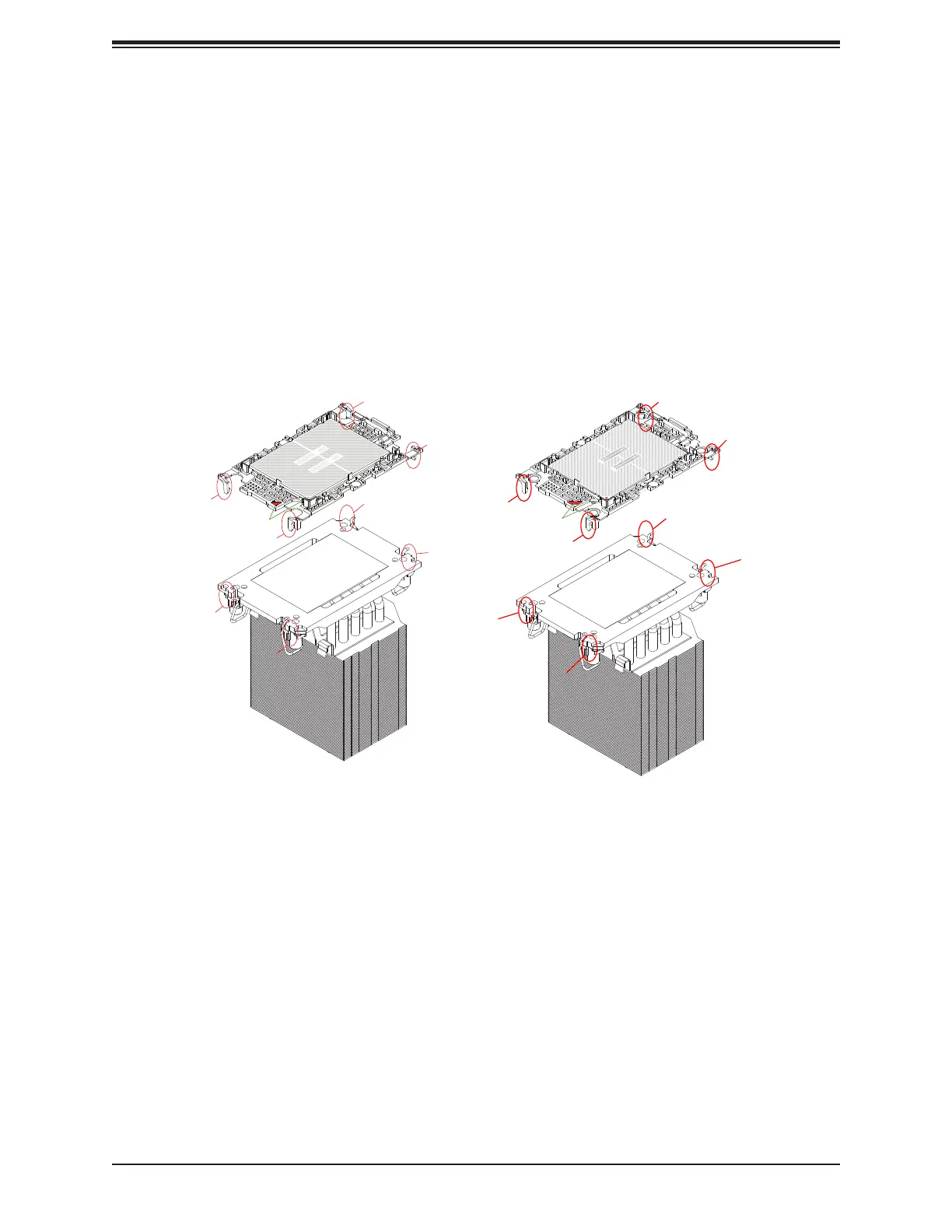
Removing the Processor Carrier Assembly from the PHM
To remove the processor carrier assembly from the PHM, please follow the steps below.
1. Detach the four plastic clips (marked a, b, c, d) on the processor carrier assembly from
the four corners of the heatsink (marked A, B, C, D) as shown below.
4U Heatsink (Bottom View)
a
c
d
A
B
(CPU2) Pin 1
Processor Carrier Assembly
(Component Side)
(SP MCC, Carrier E1B)
a
c
A
C
B
(CPU2) Pin 1
Processor Carrier Assembly
(Component Side)
(SP XCC, Carrier E1A)
 Loading...


