52
Super X13DAI-T User's Manual
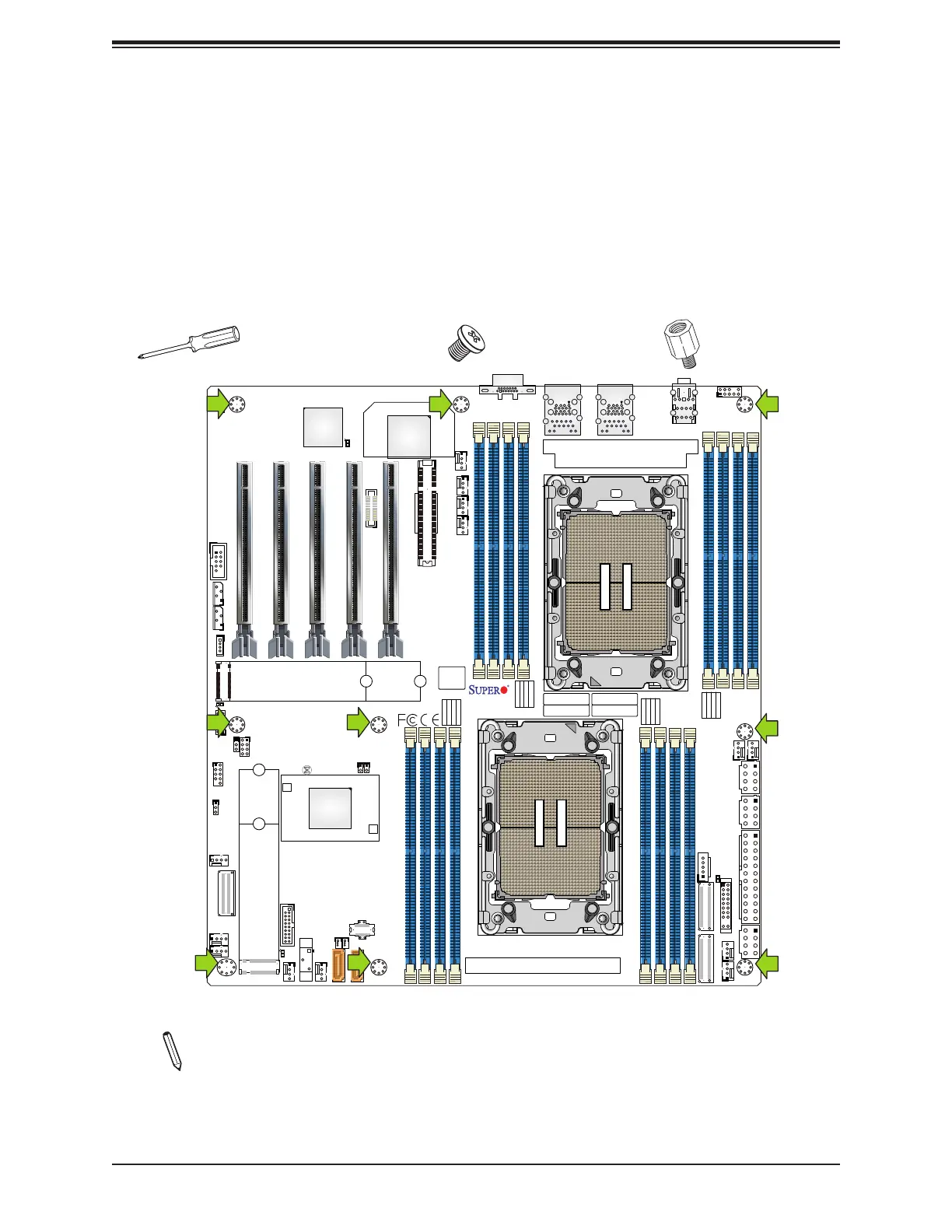
2.3 Motherboard Installation
All motherboards have standard mounting holes to t dierent types of chassis. Make sure
that the locations of all the mounting holes for both the motherboard and the chassis match.
Although a chassis may have both plastic and metal mounting fasteners, metal ones are
highly recommended because they ground the motherboard to the chassis. Make sure that
the metal standos click in or are screwed in tightly.
Phillips Screwdriver (1)
Standos (9)
(Only if Needed)
Phillips Screws (9)
Tools Needed
Locations of Mounting Holes
Note 1: To avoid damaging the motherboard and its components, please do not use
a force greater than 8 lbf-in on each mounting screw during motherboard installation.
Note 2: Some components are very close to the mounting holes. Please take precau-
tionary measures to avoid damaging these components when installing the mother-
board to the chassis.
CPU2
CPU1
DESIGNED IN USA
MAC CODE
IPMI CODE
BAR CODE
CM CODE
X13DAI-T
REV:1.00
BIOS
LICENSE
BT1
MH13
MH12
MH11MH10
JAUDIO1
T-SGPIO1
JPI2C1
JNCSI1
JSD2JSD1
JBT1
JS1
LEDBMC1
LED4
LED7
LEDPWR1
JF1
JPWR1
JPWR3
JPWR2
JPWR4
JNVI2C1
JIPMB1
JPG1
JTP1
JPTG1
JL1
JVRM1
JVRM2
JTPM1
JRK1
FANC
FAN6
FAN7
FAN5
FAN8
FAN9
FAN10
FANB
FANA
FAN1
FAN2
FAN3
FAN4
LAN
CTRL
AUDIO FP
USB8 (3.1 Gen 2)
P1_NVME0/1
P2_NVME0/1
(NVME ONLY)
M.2-C1
(PWR I2C)
COM1
(SATA0~7)
I-SATA9
I-SATA8
USB0/1
(CLEAR CMOS)
USB6/7 (3.0)
P1-DIMMF1
P1-DIMME1
P1-DIMMH1
P1-DIMMG1
P2-DIMMD1
P2-DIMMB1
P2-DIMMA1
P2-DIMMC1
P1-DIMMB1
P1-DIMMA1
P1-DIMMD1
P1-DIMMC1
P2-DIMMG1
P2-DIMMH1
P2-DIMME1
P2-DIMMF1
VGA
(JPCIE1) P1 SLOT1 PCIe 5.0 x16
(JPCIE2)
P2 SLOT2 PCIe 5.0 x16
(JPCIE3)
P1 SLOT3 PCIe 5.0 x16
(JPCIE4)
P2 SLOT4 PCIe 5.0 x16
(JPCIE6)
P2 SLOT6 PCIe 5.0 x8
(JPCIE5)
P1 SLOT5 PCIe 5.0 x16
BMC
(NVME ONLY)
M.2-C2
PCH
USB2/3 (3.0)
LAN1
USB4/5 (3.0)
LAN2
 Loading...


