73
Chapter 2: Installation
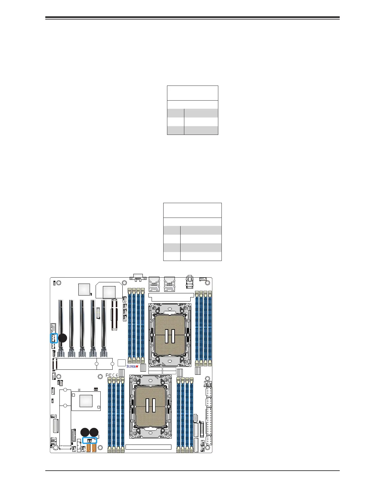
1. Disk-On-Module (DOM) Power
Connector (JSD1)
2. Disk-On-Module (DOM) Power
Connector (JSD2)
3. NVMe SMBus (I
2
C) Header
(JNVI2C1)
Disk-On-Module Power Connector
The Disk-On-Module (DOM) power connectors at JSD1 and JSD2 provide 5V power to a
solid-state DOM storage devices connected to one of the SATA ports. Refer to the table
below for pin denitions.
DOM Power
Pin Denitions
Pin# Denition
1 5V
2 Ground
3 Ground
CPU2
CPU1
DESIGNED IN USA
MAC CODE
IPMI CODE
BAR CODE
CM CODE
X13DAI-T
REV:1.00
BIOS
LICENSE
BT1
MH13
MH12
MH11MH10
JAUDIO1
T-SGPIO1
JPI2C1
JNCSI1
JSD2JSD1
JBT1
JS1
LEDBMC1
LED4
LED7
LEDPWR1
JF1
JPWR1
JPWR3
JPWR2
JPWR4
JNVI2C1
JIPMB1
JPG1
JTP1
JPTG1
JL1
JVRM1
JVRM2
JTPM1
JRK1
FANC
FAN6
FAN7
FAN5
FAN8
FAN9
FAN10
FANB
FANA
FAN1
FAN2
FAN3
FAN4
LAN
CTRL
AUDIO FP
USB8 (3.1 Gen 2)
P1_NVME0/1
P2_NVME0/1
(NVME ONLY)
M.2-C1
(PWR I2C)
COM1
(SATA0~7)
I-SATA9
I-SATA8
USB0/1
(CLEAR CMOS)
USB6/7 (3.0)
P1-DIMMF1
P1-DIMME1
P1-DIMMH1
P1-DIMMG1
P2-DIMMD1
P2-DIMMB1
P2-DIMMA1
P2-DIMMC1
P1-DIMMB1
P1-DIMMA1
P1-DIMMD1
P1-DIMMC1
P2-DIMMG1
P2-DIMMH1
P2-DIMME1
P2-DIMMF1
VGA
(JPCIE1) P1 SLOT1 PCIe 5.0 x16
(JPCIE2)
P2 SLOT2 PCIe 5.0 x16
(JPCIE3)
P1 SLOT3 PCIe 5.0 x16
(JPCIE4)
P2 SLOT4 PCIe 5.0 x16
(JPCIE6)
P2 SLOT6 PCIe 5.0 x8
(JPCIE5)
P1 SLOT5 PCIe 5.0 x16
BMC
(NVME ONLY)
M.2-C2
PCH
USB2/3 (3.0)
LAN1
USB4/5 (3.0)
LAN2
1 2
3
NVMe SMBus Header
The NVMe SMBus (I2C) header (JNVI2C1), used for PCIe SMBus clock and data connections,
provides hot-plug support via a dedicated SMBus interface. This feature is only available for
a Supermicro complete system with an Supermicro-proprietary NVMe add-on card and a
proper cable installed. Refer to the table below for pin denitions.
NVMe SMBus Header
Pin Denitions
Pin# Denition
1 Data
2 Ground
3 Clock
4 VCCIO
 Loading...


