78
Super X13DAI-T User's Manual
CPU2
CPU1
DESIGNED IN USA
MAC CODE
IPMI CODE
BAR CODE
CM CODE
X13DAI-T
REV:1.00
BIOS
LICENSE
BT1
MH13
MH12
MH11MH10
JAUDIO1
T-SGPIO1
JPI2C1
JNCSI1
JSD2JSD1
JBT1
JS1
LEDBMC1
LED4
LED7
LEDPWR1
JF1
JPWR1
JPWR3
JPWR2
JPWR4
JNVI2C1
JIPMB1
JPG1
JTP1
JPTG1
JL1
JVRM1
JVRM2
JTPM1
JRK1
FANC
FAN6
FAN7
FAN5
FAN8
FAN9
FAN10
FANB
FANA
FAN1
FAN2
FAN3
FAN4
LAN
CTRL
AUDIO FP
USB8 (3.1 Gen 2)
P1_NVME0/1
P2_NVME0/1
(NVME ONLY)
M.2-C1
(PWR I2C)
COM1
(SATA0~7)
I-SATA9
I-SATA8
USB0/1
(CLEAR CMOS)
USB6/7 (3.0)
P1-DIMMF1
P1-DIMME1
P1-DIMMH1
P1-DIMMG1
P2-DIMMD1
P2-DIMMB1
P2-DIMMA1
P2-DIMMC1
P1-DIMMB1
P1-DIMMA1
P1-DIMMD1
P1-DIMMC1
P2-DIMMG1
P2-DIMMH1
P2-DIMME1
P2-DIMMF1
VGA
(JPCIE1) P1 SLOT1 PCIe 5.0 x16
(JPCIE2)
P2 SLOT2 PCIe 5.0 x16
(JPCIE3)
P1 SLOT3 PCIe 5.0 x16
(JPCIE4)
P2 SLOT4 PCIe 5.0 x16
(JPCIE6)
P2 SLOT6 PCIe 5.0 x8
(JPCIE5)
P1 SLOT5 PCIe 5.0 x16
BMC
(NVME ONLY)
M.2-C2
PCH
USB2/3 (3.0)
LAN1
USB4/5 (3.0)
LAN2
1
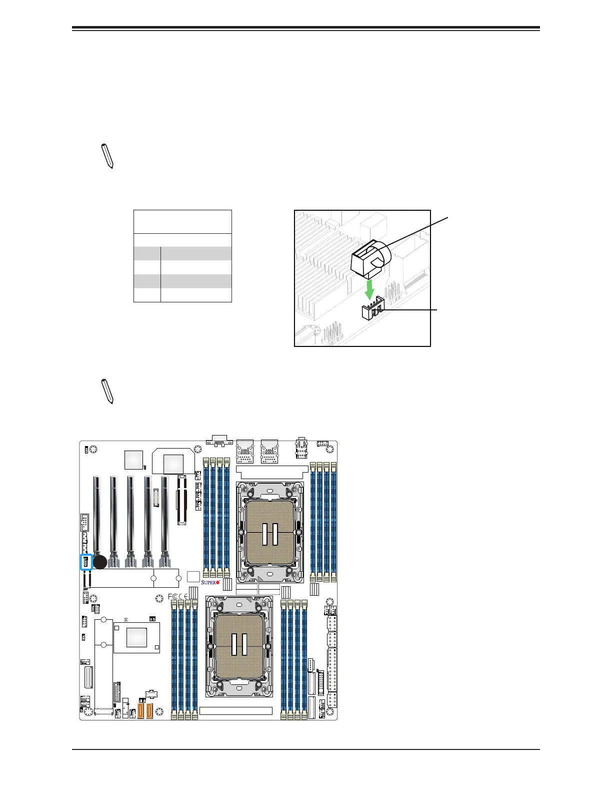
1. VROC RAID Key Header (JRK1)
VROC Key
Intel VROC Key
Pin Denitions
Pin# Denition
1 Ground
2 3.3V Standby
3 Ground
4 PCH RAID Key
VROC Key Header (JRK1)
Note: The graphics contained in this user's manual are for illustration only. The compo-
nents installed in your system may or may not look exactly the same as the graphics
shown in the manual.
VROC RAID Key Header
An Intel VROC RAID Key header is located at JRK1 on the motherboard. Install a VROC
RAID Key on JRK1 for NVMe RAID support as shown in the illustration below. Please refer
to the layout below for the location of JRK1.
Note: For detailed instructions on how to congure VROC RAID settings, please refer
to the VROC RAID Conguration User's Guide posted on the web page under the link:
https://www.supermicro.com/support/manuals/.
 Loading...


