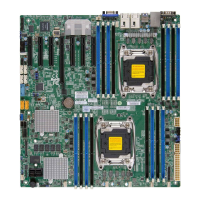
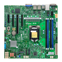
38
Super X13SAE/X13SAE-F User's Manual
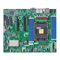
DIMMA1
DIMMA2
DIMMB1
DIMMB2
USB11 (3.2 (20Gb))
USB4/5 (3.2 (5Gb))
USB6 (3.2 (5Gb))
LED4
BMC_HB_LED
UID
DP
HDMI
VGA
DVI
IPMI_LAN
USB0/1
LAN1
USB7 (3.2 (10Gb))
USB10 (3.2 (20Gb))
LAN2
USB8/9 (3.2 (10Gb))
JPL2
JPAC1
PCI-E M.2-M2
PCI-E M.2-M3
PCI-E M.2-M1
JPW1
CPU SLOT7 PCI-E 5.0 X16
CPU SLOT4 PCI-E 5.0 X8 (IN x16)
PCH SLOT5 PCI-E 3.0 X4
PCH SLOT2 PCI-E 3.0 X4
SLOT1 PCI 33MHZ
BMC
BT1
MAC CODE
BMC CODE
BAR CODE
MAC CODE
BIOS LICENSE
X13SAE-F
DESIGNED IN USA
REV:1.00
JPME2
JLED1
JD1
JPG1
I-SATA0
I-SATA1
I-SATA2
I-SATA3
I-SATA4
I-SATA5
I-SATA6
I-SATA7
JWD1
PWR_LED
CATERR_LED
JSTBY1
JL1
JSD1
SYS_FAN3
SYS_FAN2
SYS_FAN1
CPU_FAN2
CPU_FAN1
JPW2
12V_PUMP_PWR1
AUDIO_FP
COM1
USB2/3
JTPM1
SP1
JF1
JBT1
JPI2C1
PCH
AUDIO
JPL1
1. USB0 (USB 2.0, Type-A)
2. USB1 (USB 2.0, Type-A)
3. USB2/3 (USB 2.0)
4. USB4/5 (USB 3.2 Gen. 1)
5. USB6 (USB 3.2 Gen. 1, vertical
Type-A)
6. USB7 (USB 3.2 Gen. 2, Type-
A)
7. USB10 (USB 3.2 Gen. 2x2,
Type-C)
8. USB8 (USB 3.2 Gen. 2, Type-
A)
9. USB9 (USB 3.2 Gen. 2, Type-
A)
10. USB11 (USB 3.2 Gen. 2x2)
Universal Serial Bus (USB) Connections
There are two USB 2.0 Type-A ports (USB0, USB1), three USB 3.2 Gen. 2x1 Type-A ports
(USB7, USB8, USB9), and one USB 3.2 Gen. 2x2 Type-C port (USB10) are located on the
I/O back panel. One internal USB 3.2 Gen. 1 vertical Type-A connector (USB6) has been
built-in on the motherboard. In addition, one USB 2.0 header (USB2/3), one USB 3.2 Gen.
1 header (USB4/5), and one USB 3.2 Gen. 2x2 20-pin header (USB11) are also located on
the motherboard to provide front chassis access using USB cables (not included). Refer to
the tables below for pin denitions.
Front Panel USB2/3 (2.0)
Pin Denitions
Pin# Denition Pin# Denition
1 +5V 2 +5V
3 USB_PN2# 4 USB_PN3
5 USB_PP2 6 USB_PP3
7 Ground 8 Ground
9 Key 10 Ground
Front Panel USB4/5 (3.2 Gen. 1)
Pin Denitions
Pin# Pin# Signal Name Description
1 19 VBUS Power
2 18 StdA_SSRX- USB 2.0 Dierential Pair
3 17 StdA_SSRX+
4 13 Ground Ground of PWR Return
5 15 StdA_SSTX- SuperSpeed Receiver
6 14 StdA_SSTX+ Dierential Pair
7 16 GND_DRAIN Ground for Signal Return
8 12 D- SuperSpeed Transmitter
9 11 D+ Dierential Pair
Front Panel USB 11 (3.2 Gen. 2x2)
Pin Denitions
Pin# Denition Pin# Denition Pin# Denition Pin# Denition Pin# Denition
1 VBUS 5 RX1+ 9 NC 13 TX2- 17 GND
2 TX1+ 6 RX1- 10 NC 14 GND 18 D-
3 TX1- 7 VBUS 11 VBUS 15 RX2+ 19 D+
4 GND 8 CC1 12 TX2+ 16 RX2- 20 CC2
3
4
5
8
9
1
7
6
2
10

 Loading...
