10
Super X13SWA-TF User's Manual
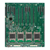
Quick Reference (for Intel Xeon W-3400 Series CPU / 112L)
5
JL1
JRK1
(RAID Key Header)
JBT1
LED8
MAC CODE
JTPM1
USB0/1
USB4/5
(USB 3.2 Gen 1)
BIOS LICENSE
BAR CODE
BAR CODE
MAC CODE
PCH
(Power LED)
AUDIO FP
COM1
USB11
(USB3.2 Gen.2x2)
JPL2
HD AUDIO
FAN6
FAND
FANC
FANB FANA
JD1
SP1
CPU
BATTERY
SATA7
U.2-2 U.2-1
SATA6
SATA5
SATA4
SATA2
SATA3
SATA0
SATA1
JPW3
JPME2
JPW2
JPW4
FAN5
FAN3 FAN4
FAN2FAN1
JPI2C1
LED1
JSTBY1
JWD1
JF1
JSD1
CPU SLOT7 PCIe 5.0 X16
JOH1
JPW1
12V_PUMP_PWR1
LAN2
(USB3.2 Gen 2x1)
USB6/7
JPUSB1
USB8/9
(USB3.2 Gen 2x1)
LAN1
USB10
(USB3.2 Gen 2X2)
JPL1
VGA
JUIDB1
CPU SLOT5 PCIe 5.0 X16
CPU SLOT6 PCIe 5.0 X16
LED4
(UID-LED)
USB2/3
BMC
CPU SLO1 PCIe 5.0 X16
CPU SLOT3 PCIe 5.0 X16
BMC LED
CPU SLOT4 PCIe 5.0 X16
JSPDIF_OUT
JPAC1
DIMMA1
DIMMA2
DIMMB2
DIMMB1
DIMMC2
DIMMC1
DIMMD2
DIMMD1
BAR CODE
BAR CODE
MAC CODE
BIOS LICENSE
PCH
(PWR I2C)
(SPEAKER 1-4)
LAN
CTRL
LAN
CTRL
DIMMG2
DIMMH1
DIMMH2
DIMMG1
DIMME2
DIMMF2
DIMMF1
DIMME1
SAS CODE
LED3
(M.2-C01 LED)
LED5
(M.2-C02 LED)
LED6
(M.2-C03 LED)
LED7 (M.2-C04 LED)
M.2-C01
(
PCIe 5.0 X4)
M.2-C02
(PCIe 5.0 X4)
M.2-C03
(PCIe 5.0 X4)
(PCIe 5.0 X4)
M.2-C04
X13SWA-TF
DESIGNED IN USA
REV:1.01
+
BMC CODE
USB2/3
LAN1
USB8/9
LAN2
USB6/7
JPUSB1
JPL2
HD AUDIO
JPW3
JPL1
FAN5
BATTERY
JPW4
12V_PUMP_PWR1
COM1
VGA
JUIDB1
USB10
DIMMB1
DIMMB2
DIMMA1
DIMMA2
DIMME2
DIMME1
DIMMF2
DIMMF1
DIMMD1
DIMMD2
DIMMC1
DIMMC2
DIMMG2
DIMMG1
DIMMH2
DIMMH1
LED4
AUDIO FPJPAC1
BMC LED
CPU SLOT3–7
CPU SLOT1
LED7
M.2-C04
LED6
M.2-C02
M.2-C01
JRK1
LED5
LED3
JL1
M.2-C03
LED8
JTPM1
USB0/1
USB4/5
JSD1
SATA0
SATA1
SATA2
SATA3
SATA5
SATA4
SATA7
SATA6
U.2-2
U.2-1
USB11
JSTBY1
JF1
FAN2 FAN4
FAN3
FAN1
JWD1
LED1
JPI2C1
JOH1
JPME2
JPW1
JD1
FANB
FANA
JBT1
FAN6
FANC
FAND
JPW2
JSPDIF_OUT
W-3400 Series CPU
Notes:
• If PCIe slot of CPU SLOT1 is to be installed with a full-length PCIe card (longer than
238mm), please use a horizontal TPM module for JTPM1 to prevent mechanical conict.
• See Chapter 2 for detailed information on jumpers, I/O ports, and JF1 front panel connec-
tions.
• " " indicates the location of Pin 1.
• Jumpers/LED indicators not indicated are used for testing only.
• Use only the correct type of onboard CMOS battery as specied by the manufacturer. Do
not install the onboard battery upside down to avoid possible explosion.

 Loading...