13
Chapter 1: Introduction
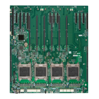
Connector Description
12V_PUMP_PWR1 12V 4-pin Power Connector for CPU Liquid Cooling Pump
AUDIO FP Front Panel Audio Header
BATTERY Onboard Battery
COM1 COM Port (Back Panel)
CPU SLOT1/3/4/5/6/7
PCIe 5.0 x16 Slots
Note: For W-2400 (64L) CPU, only SLOT3/5/7 are supported.
FAN1 – FAN6 CPU Fan Headers
FANA – FAND System Fan Headers
HD AUDIO Back Panel High Denition Audio Port
JD1 Speaker/Buzzer Header
JF1 Front Control Panel Header
JL1 Chassis Intrusion Header
JOH1 Overheat LED Header
JPI2C1 Power Supply SMBus I
2
C Header
JPW1 24-pin ATX Main Power Connector (Required)
JPW2, JPW3, JPW4 +12V 8-pin CPU Power Connectors
JRK1
Intel VROC Key Header
Note: A VROC hardware key is required for VROC RAID function.
JSD1 SATA DOM (Disk-On-Module) Power Connectors
JSPDIF_OUT Sony/Philips Digital Interface (S/PDIF) Out Header
JSTBY1 Standby Power Header (5V)
JTPM1
Trusted Platform Module (TPM)/Port 80 Header
Note: If CPU SLOT1 is to be installed with a full-length PCIe card, please use a horizontal TPM
module for JTPM1 to prevent mechanical conict.
JUIDB1 Unit Identier (UID) Switch / BMC Reset Button
LAN1 RJ45 1GbE LAN Port (Shared IPMI Port)
LAN2 RJ45 10GbE LAN Port
M.2-C01 – M.2-C04
PCIe 5.0 x4 M.2 M-key Sockets (Support 22110/2280 form factors and RAID 0/1/5/10)
Note: Please use wide temperature (up to 85°C) M.2 devices for M.2-C4 and M.2-C3.
SATA0 – SATA7 Intel Serial ATA (SATA 3.0) Ports 0 – 7 (6Gb/second) (Support RAID 0/1/5/10)
SP1 Internal Speaker/Buzzer
U.2-1, U.2-2 PCIe 3.0 x4 U.2 Connectors 1 and 2 for NVMe 2.5" SSDs (Support RAID 0/1)
USB0/1 Front Access USB 2.0 Header
USB2, USB3 Back Panel USB 2.0 Ports (Type-A)
USB4/5 Front Access USB 3.2 Gen. 1 Header (5Gb, Type-A)
USB6, USB7, USB8, USB9 Back Panel USB 3.2 Gen. 2x1 Ports (10Gb, Type-A)
USB10 Back Panel USB 3.2 Gen. 2x2 Port (20Gb, Type-C)
USB11 Front Access USB 3.2 Gen. 2x2 Header (20Gb, Type-C)
VGA VGA Port (IPMI only)
Note: For detailed instructions on how to congure VROC RAID settings, please refer
to the VROC RAID Conguration User's Guide posted on the web page under the link:
https://www.supermicro.com/support/manuals/.

 Loading...