2-12
X7DB8-X/X7DBE-X User's Manual
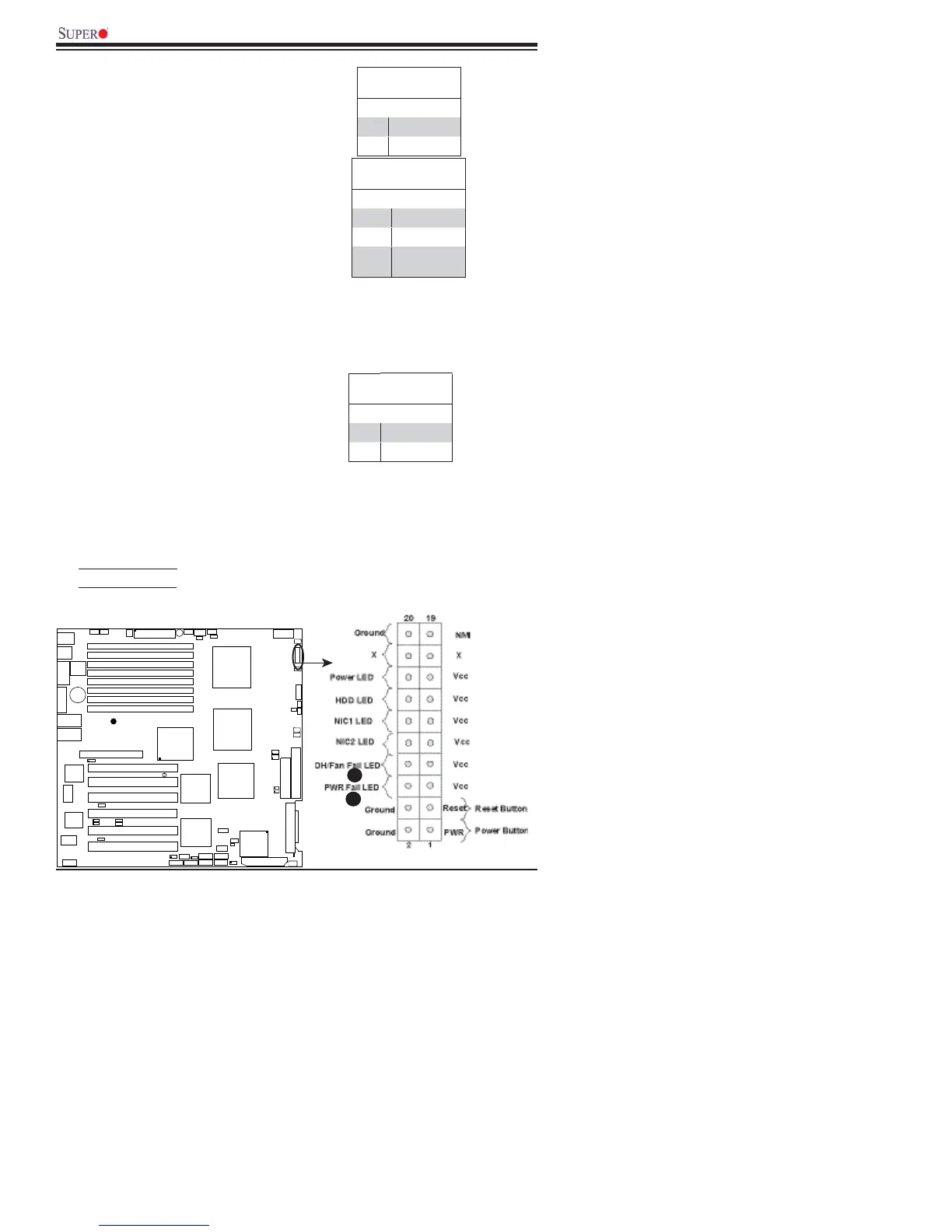
Overheat/Fan Fail LED (OH)
Connect an LED to the OH/Fan Fail
connection on pins 7 and 8 of JF1
to provide a warning in the event of
chassis overheating or fan failure.
Refer to the table on the right for pin
defi nitions.
Power Fail LED
The Power Fail LED connection is
located on pins 5 and 6 of JF1. Re-
fer to the table on the right for pin
defi nitions.
OH/Fan Fail LED
Pin Defi nitions (JF1)
Pin# Defi nition
7 Vcc
8 Ground
OH/Fan Fail Indicator
Status
State Defi nition
Off Normal
On Overheat
Flash-
ing
Fan Fail
PWR Fail LED
Pin Defi nitions (JF1)
Pin# Defi nition
5 Vcc
6 Ground
A
B
A. OH/Fan Fail LED
B. PWR Supply Fail
GLAN1
®
S
UPER X7DB8/E-X
GLAN2
8-pin PW R
FP Ctrl
SPK
PW LED
JOH1
F
a
n
3
IDE1
Fl
oppy
BIOS
320 SC S I Channel A
F
a
n
4
S
A
T
A
1
S
A
T
A
0
U
S
B2/
3
S
MB
PCI
-
X100MHz(ZC
R
-
X7DB8 onl
y
)
PCI
-
X1
3
3
MH
z
J
W
D
B
at
t
er
y
V
GA
C
TR
L
No
r
t
h
Bri
d
g
e
V
GA
CO
M
1
US
B0/
1
KB/
M
ou
s
e
Fa
n6
Fa
n5
A
T
XP
W
R
4-
P
in
P
W
R
J3P
24
-Pin
JP
G1
SCSI CTRL
C
P
U
1
C
P
U
2
South
Bridg
e
P
X
H
D
IMM 1A
(
B
a
nk
1
)
Fa
n7
JAR
PSF
LE1
J
P
A
2
J
P
A
3
JPA1
320 S CS I C hannel B
S
A
T
A
3
S
A
T
A
2
S
A
T
A
4
S
A
T
A
5
J
L1
J
K
1
Slot1
Sl
ot2
Sl
ot3
PCI
-
X
1
33 MH
z
S
l
o
t4
J
P
L
1
JP
L
2
Sl
ot5
Slot6
SIMLP IPMI
S
lot7
D
IMM
1
B
(
B
ank
1
)
D
IMM
2
A
(
B
a
n
k
2
)
D
IMM
2
B
(
B
ank 2)
D
IMM 3A
(
B
a
nk
3
)
D
IMM 3B
(
B
ank 3)
D
I
MM 4A
(
B
a
nk
4
)
D
I
MM 4B
(
B
ank 4)
JB
T1
U
S
B
4
J
W
O
R
1
COM
2
D
A
2
W
OL
D
A
1
S
I/O
JP1
L
AN
CT
RL
J
2
7
J
2
8
SG
P
IO
1
SG
PIO
2
SMBPS
PCI
-
X
1
0
0
M
Hz
PC
I
-X 100 MHz
PCI
-X 133 MHz
Video
Memory
P
X
H
F
a
n
8
F
a
n2
F
a
n
1
Buzzer
5000P
ESB2
Adaptec 7902