Do you have a question about the Supermicro X7DB8-X and is the answer not in the manual?
Details the manual's purpose, target audience, and scope.
Outlines the structure and content of each chapter and appendix.
Explains symbols and formatting used for warnings and notes.
Introduces the motherboard and lists included accessories.
Details the functionality and components of the 5000P chipset.
Describes unique functionalities like AC power loss recovery.
Explains system monitoring features for voltage, fans, and temperature.
Provides a quick lookup for jumpers and connectors.
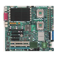
Lists key hardware features of the motherboard (CPU, Memory, Chipset, Slots, BIOS, etc.).
Details Advanced Configuration and Power Interface features.
Describes onboard input/output ports and controllers.
Lists additional features like modem ring-on and WOL.
Provides physical dimensions of the motherboard.
Describes BIOS setting for system response to AC power loss.
Details system monitoring features for voltage, fans, and temperature.
Explains CPU fan behavior during sleep mode.
Describes LED indicators and controls for CPU overheating.
Details alerts for system resource issues using Supero Doctor.
Explains how the power button functions for system suspend and shutdown.
Describes wake-up events triggered by modem ring-on.
Details the functionality of Wake-On-LAN for remote power-up.
Specifies requirements for ATX power supplies and the 12V 4-pin connector.
Describes the functions of the Super I/O chip for disk drives and ports.
Precautions and procedures for handling static-sensitive components.
Guides on installing the CPU and its heatsink/fan assembly.
Procedures for installing and uninstalling the CPU heatsink.
Instructions for securing the motherboard within the computer chassis.
Step-by-step instructions for installing memory modules.
Identifies back panel I/O ports and their definitions.
Describes front panel connectors and their functions.
Specific pin definitions for NMI button and Power LED.
Details the pin definitions for the Hard Drive LED indicator.
Explains LED indicators for network interface cards.
Describes LED for chassis overheating or fan failure warnings.
Details the pin definition for the Power Fail LED indicator.
Explains the connection for the system reset button.
Details the connection and function of the power button.
Details ATX and CPU power connector pin definitions.
Describes the location and pin definitions of USB ports and headers.
Explains the chassis intrusion header connection.
Details the pin definitions and types of fan headers.
Explains the keyboard lock connection for security.
Provides pin definitions for keyboard and mouse ports.
Details pin definitions for COM1 and COM2 serial ports.
Describes the header and function of the Wake-On-Ring feature.
Details the header and function of the Wake-On-LAN feature.
Describes the two Gigabit Ethernet ports and their RJ45 connectors.
Explains the header for power LED and onboard/external speaker.
Details the Power Fail header for power supply failure warnings.
Describes the Alarm Reset header for power module failure notification.
Describes the header for overheat and fan failure LEDs.
Explains the System Management Bus header connection.
Details the pin definitions for the Power SMB connector.
Identifies the location of the VGA connector.
Describes the SGPIO headers for SATA/SAS connectors.
Explains the function and settings of motherboard jumpers.
Instructions for clearing the CMOS settings.
Explains the Watch Dog timer jumper settings.
Describes the jumper for enabling/disabling the SCSI controller.
Explains jumpers for SCSI channel termination.
Details the jumper for detecting third power supply failure.
Describes the jumper for enabling or disabling the VGA port.
Explains jumpers for connecting I2C to PCI-X slots.
Details the function of onboard LEDs for system status.
Details onboard LEDs for SCSI channel activity.
Explains the function of the onboard power indicator LED.
Describes connections for floppy, hard disk, IPMI, and SCSI.
Identifies the location of the SIM Low Profile IPMI Slot.
Details the pin definitions for the IDE connector.
Details pin definitions for Ultra 320 SCSI connectors.
General steps to diagnose and resolve system issues.
Lists common memory installation and configuration issues.
Outlines steps to take before contacting technical support.
Answers common questions regarding memory, BIOS updates, and CD contents.
Explains the process for returning products for warranty service.
Introduces the Phoenix BIOS Setup utility and its features.
Explains how to access and navigate the BIOS Setup utility.
Describes the main BIOS Setup screen and navigation.
Settings for configuring IDE and SATA drive parameters.
Displays recognized system memory and extended memory.
Introduces the Advanced Setup menu for detailed system configurations.
Settings related to system boot behavior and POST.
Configuration options for system memory caching.
Controls MTRR configuration for graphics effects.
Settings for configuring PCI devices and slots.
Settings for various PCI-X slots like Option ROM Scan and Latency Timer.
Determines how memory branches operate (Interleave, Sequential, etc.).
Enables or disables USB device functionality.
Settings for CPU features like Hyper-Threading and Virtualization.
Enables one platform to run multiple operating systems.
Enables dynamic adjustment of CPU voltage and frequency.
Configuration options for serial ports, floppy controller, and KBC clock.
Management and viewing of DMI event logs.
Configuration for redirecting console output over serial ports.
Monitors system hardware like CPU temperature, fan speed, and voltage.
Configuration for Intelligent Platform Management Interface.
Displays System Event Log entries.
Displays real-time data from motherboard sensors (temp, fan, voltage).
Settings for BIOS supervisor and user passwords.
Requires a password for system boot-up.
Configuration of boot device priority and boot options.
Options for exiting the BIOS setup utility.
POST message indicating a problem with the fixed disk drive.
POST error indicating system RAM failure at a specific offset.
POST message indicating a dead CMOS battery.
POST error indicating corrupted CMOS data.
POST error indicating a problem with the floppy drive A.
POST error related to incorrect NVRAM (CMOS) data.
POST message indicating no operating system was found.
POST error indicating parity error in the system bus.
Explains the function of keys like F1, F2, F3 during POST.
Indicates system BIOS has been copied to shadow RAM.
Indicates video BIOS has been copied to shadow RAM.
Describes POST errors that allow the system to continue.
Describes POST errors that cause the system to shut down.
Lists POST codes specific to the boot block in Flash ROM.
Introduces Serial ATA and Parallel ATA interfaces.
Lists supported Intel HostRAID configurations (RAID 0, 1, 10, 5).
Explains Intel Matrix Storage for creating RAID sets.
Step-by-step guide to configure SATA RAID in BIOS.
Step-by-step instructions for creating a RAID 0 volume.
Step-by-step instructions for creating a RAID 1 volume.
Step-by-step instructions for creating a RAID 10 volume.
Step-by-step instructions for creating a RAID 5 volume.
Instructions for deleting a RAID volume.
Resets RAID drives to non-RAID or resets RAID HDD.
Introduces Adaptec SATA RAID Controller and its features.
Steps to configure Adaptec SATA RAID for OS installation.
Utility for creating, configuring, and managing RAID arrays.
Options to view array properties and configure settings.
Steps to configure individual disk drives for use.
Steps to create new RAID arrays.
Assigns properties like label, stripe size, and creation method.
Makes a RAID array bootable.
Removes bootable status from a RAID array.
Adds or removes hot spare drives for RAID arrays.
Displays detailed information about existing RAID arrays.
Restores functionality of fault-tolerant arrays.
Deletes existing RAID arrays and partitions.
Formats or verifies Serial ATA hard disk media.
Steps for formatting a disk using the utility.
Scans disk media for defects.
Exits the RAID configuration utility.
Installs drivers for chipset, audio, etc., after OS installation.
Configures Supero Doctor III for system monitoring.
| Brand | Supermicro |
|---|---|
| Model | X7DB8-X |
| Category | Motherboard |
| Language | English |