Chapter 2: Overview
2-5
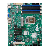
Connectors Description
JBAT1 Onboard Battery
COM1/COM2 COM1/COM2 Serial Connections
FAN 1~8 CPU//System Fan Headers (Fans 7, 8: CPU
Fans)
IPMB 4-pin BMC I
2
C Header (for an IPMI Card)
I-SATA 0~5 Intel SB SATA Connectors 0~5
JD1 Speaker/Power LED Indicator
JF1 Front Panel Control Header
JL1 Chassis Intrusion
JPI
2
C1 Power Supply SMBbus I
2
C Header
JPW1 ATX 24-Pin Power Connector (See Warning
on Pg. 2-6.)
JPW2/JPW3 12V 8-Pin Power Connectors (See Warning
on Pg. 2-6.)
JPTM1 Trusted Platform Support Header
JWF1 SATA DOM (Disk_On_Module) PWR
JWOR1 Wake_On_Ring Header
KB/MS PS2 Keyboard/Mouse
LAN1/LAN2 G-bit Ethernet Ports 1/2
(IPMI) LAN IPMI_Dedicated LAN
SP1 Onboard Buzzer (Internal Speaker)
T-SGPIO 1/2 Serial_Link General Purpose I/O Headers
USB 0/1, 2/3 Back Panel USB 0/1, 2/3
USB 4/5, 6/7, 8, 10 Front Panel Accessible USB Connections
UID SW1 UID (Universal Identifi er) Switch
VGA Backpanel VGA Port
LED Description State Status
LE1 Standby PWR LED Green: On PWR On
LE2 UID Switch LED Blue Unit Identifi ed
LEM1 BMC Heartbeat LED Green: Blinking BMC Normal
Warning!
To prevent damage to the power supply or motherboard, please use a
power supply that contains a 24-pin and two 8-pin power connectors.
Be sure to connect these connectors to the 24-pin (JPW1) and the two
8-pin (JPW2,JPW3) power connectors on the motherboard. Failure in
doing so will void the manufacturer warranty on your power supply and
motherboard.
 Loading...