Power Button
Blue+ (OH/Fan Fail/
PWR FaiL/UID LED)
1
NIC1 Link LED
Reset Button
2
Power Fail LED
HDD LED
FP PWRLED
Reset
PWR
3.3 V
ID_UID_SW/3/3V Stby
Red+ (Blue LED Cathode)
Ground
Ground
1920
3.3V
X
Ground
NMI
X
NIC2 Link LED
NIC2 Activity LED
NIC1 Activity LED
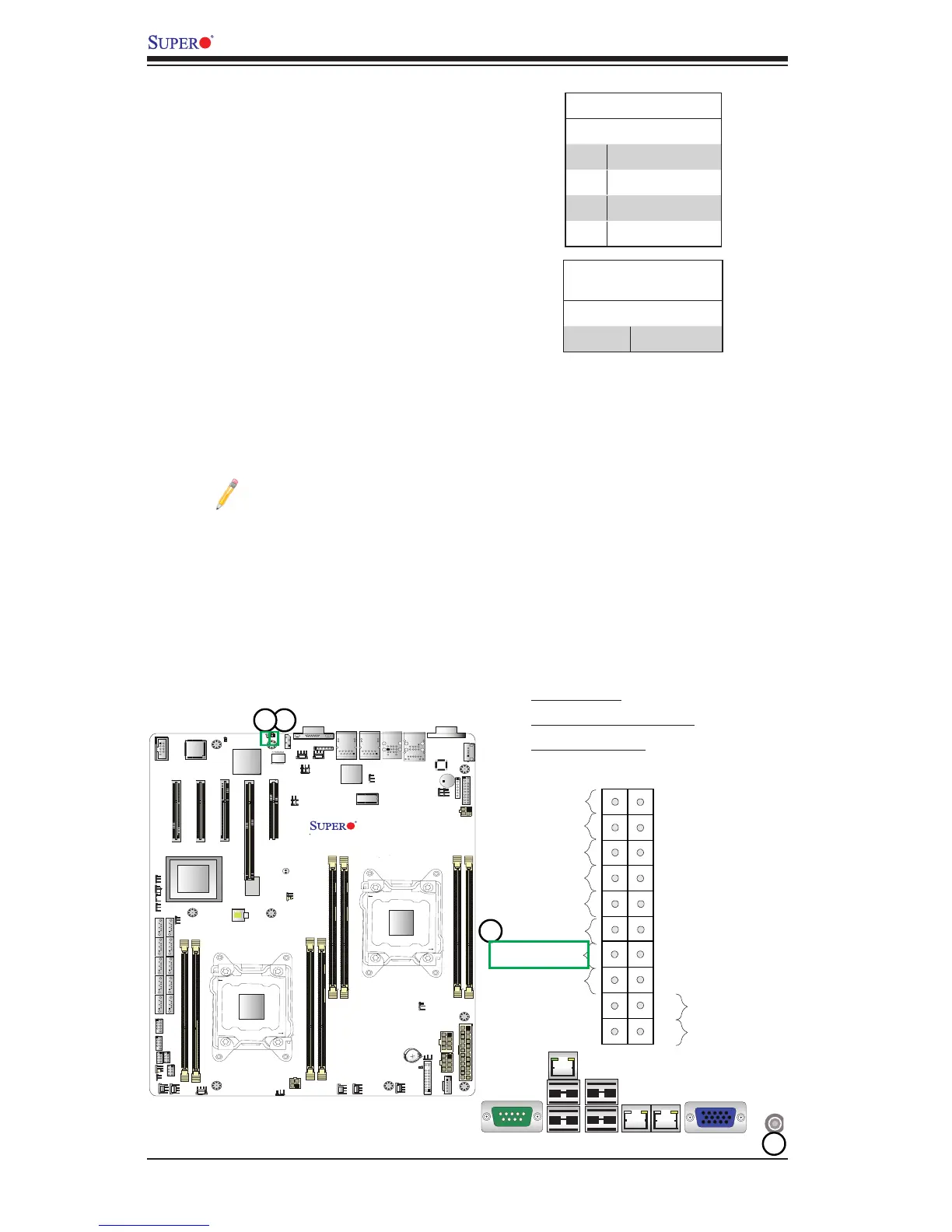
UnitIdentierSwitch/UIDLEDIndicators
A Unit Identier (UID) Switch and two LED Indi-
cators are located on the motherboard. The UID
Switch is located next to the VGA port on the
backplane. The Rear UID LED (LED3) is located
next to the UID Switch. The Front Panel UID
LED is located at pins 7/8 of the Front Control
Panel at JF1. Connect a cable to pin 8 on JF1
for Front Panel UID LED indication. When you
press the UID switch, both Rear UID LED and
Front Panel UID LED Indicators will be turned
on. Press the UID switch again to turn off both
LED Indicators. These UID Indicators provide
easy identication of a system unit that may be
in need of service.
Note: UID can also be triggered via
IPMI on the motherboard. For more
information on IPMI, please refer to the
IPMI User's Guide posted on our web-
site @ http://www.supermicro.com.
UID Switch
Pin# Denition
1 Ground
2 Ground
3 Button In
4 Ground
1. UID Switch
2. Rear UID LED (LED3)
3. Front UID LED
UID LED (LED3)
Status
Color/State Status
Blue: On Unit Identied

 Loading...


