Do you have a question about the Supermicro X9DA7 and is the answer not in the manual?
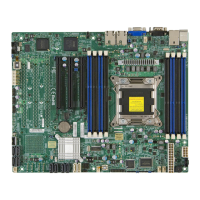
Details the Super X9DA7/X9DAE motherboard's features and capabilities.
Outlines the structure and content of the user manual's chapters.
Explains symbols indicating important safety and damage prevention information.
Explains symbols indicating additional information or tips.
Provides contact details for Supermicro's Headquarters, Europe, and Asia-Pacific offices.
General introduction to the motherboard, its design, and retail box contents.
Details the Intel E5-2600(v2) processors and the Intel C602 chipset.
Highlights key features like ACPI, Rapid Storage Technology, and memory support.
Describes onboard monitoring for voltages, fans, and temperatures.
Explains the Advanced Configuration and Power Interface specifications.
Specifies power supply requirements, including connector types and ratings.
Details the Super I/O chip's capabilities for serial ports and power management.
Industry-standard warnings for user safety during installation.
Warning and instructions for safe battery replacement and disposal.
Measures to protect against electrostatic discharge and safe unpacking procedures.
Step-by-step guide for installing the CPU into the LGA2011 socket.
Guide for installing and removing DIMM memory modules into slots.
Lists required tools, identifies mounting holes, and provides safety cautions.
Overview and definitions of the motherboard's rear I/O ports.
Details various ways to connect keyboard and mouse devices.
Pin definitions for the NMI button and Power LED indicators.
General explanation of how jumpers are used for configuration.
Setting to enable or disable the onboard GLAN ports.
Information on LAN port activity/link LEDs and the onboard power LED status.
Description and pin definitions for SATA and SAS ports.
General procedures for system troubleshooting.
Initial checks and steps for diagnosing no-power problems.
Steps for diagnosing and resolving memory-related errors.
Verifies CPU/BIOS, memory, HDD, and cooling for system stability.
Steps for battery removal, installation, and proper disposal.
Introduction to the BIOS utility and how to enter setup.
Settings related to the boot process, including quiet boot and F1 error wait.
Details on installed CPUs and their configuration options like speed and cores.
Settings for Intel North Bridge and IOH, including VT-d and I/OAT.
Settings for QPI link speed and frequency selection.
Settings for memory modes, mirroring, and sparing.
Enables/disables USB devices and EHCI controllers.
Enables/disables Azalia HD Audio and HDMI Decode.
Configures SATA mode (IDE, AHCI, RAID).
Settings for PCI ROM booting and latency.
Settings for 4G decoding and error generation (PERR#/SERR#).
Enables/disables serial port and configures device settings.
Enables/disables Watch Dog timer.
Settings for fan speed control and CPU temperature display.
Selects ACPI sleep state and Numa support.
Settings for TPM support and status.
Settings for configuring event logs.
Specifies boot device sequence and legacy device order.
Deletes a defined boot device.
Sets BIOS administrator and user passwords.
Options to quit BIOS with or without saving.
Table listing beep codes, error messages, and descriptions.
Guide for installing drivers and utilities.
| Microphone in | Yes |
|---|---|
| PS/2 ports quantity | 2 |
| Serial ports quantity | 1 |
| USB 2.0 ports quantity | USB 2.0 ports have a data transmission speed of 480 Mbps, and are backwards compatible with USB 1.1 ports. You can connect all kinds of peripheral devices to them. |
| USB 2.0 connectors | 3 |
| Integrated SAS ports | 8 |
| Number of SATA II connectors | 6 |
| Maximum UDIMM memory | 128 GB |
| Number of DIMM slots | 16 |
| Supported RDIMM clock speeds | 800, 1066, 1333, 1600 MHz |
| Supported DIMM module capacities | 16GB, 1GB, 2GB, 32GB, 4GB, 8GB |
| PCI Express slots version | 3.0 |
| Memory voltage | 1.35, 1.5 V |
| Maximum RDIMM memory | 512 GB |
| Supported memory types | DDR3-SDRAM |
| BIOS type | AMI |
| ACPI version | 4.0 |
| BIOS memory size | 128 Mbit |
| RAID levels | 0, 1, 5, 10 |
| Supported storage drive interfaces | Serial Attached SCSI (SAS) |
| Wi-Fi | No |
| LAN controller | Intel® I350 |
| Ethernet interface type | Gigabit Ethernet |
| Cables included | FireWire, SATA |
| Bundled software | SuperDoctor® III Watch Dog, NMI |
| Storage temperature (T-T) | -40 - 70 °C |
| Operating temperature (T-T) | 10 - 35 °C |
| Storage relative humidity (H-H) | 5 - 95 % |
| Operating relative humidity (H-H) | 8 - 90 % |
| Supported QPI | 6.4, 7.2, 8 GT/s |
| Processor socket | LGA 2011 (Socket R) |
| Intel Xeon series | E5-2600 |
| Processor manufacturer | Intel |
| Processor thermal power (max) | 150 W |
| Processor number of cores supported | 4, 6, 8 |
| Component for | Workstation |
| Motherboard chipset | Intel® C602 |
| Audio output channels | 7.1 channels |
| Motherboard form factor | Extended ATX |
| Sustainability certificates | RoHS |
| Depth | 332 mm |
|---|---|
| Width | 305 mm |

