2-30
X9DA7/X9DAE Motherboard User's Manual
JPWR1
JPI2C1
LE1
JTPM1
FAN5
FAN7
FAN6
FAN2
FAN3
FAN1
J18
JSD1
SP1
J29
JBR1
JWD1
STBY1
JPI1
JL1
CPU1
P2 DIMMH2
P2 DIMMG2
P2 DIMMH1
P2 DIMMG1
P2 DIMME2
P2 DIMMF1
P2 DIMMF2
P1 DIMMA2
P1 DIMMA1
P1 DIMMB2
P1 DIMMB1
P1 DIMMD2
P1 DIMMD1
J25
CPU2 Slot5 PCI-E 3.0 x16
CPU1 Slot3 PCI-E 3.0 x16
CPU2 Slot2 PCI-E 3.0 x4 in x8
TPM/Port80
JF1
Always Populate DIMMxA First
CPU2
S-SATA3
I-SATA1
COM1
USB3.0 0/1
S-SATA0
P1 DIMMC2
P1 DIMMC1
JSPDIF_In
JBT1
JPME1
BIOS
JD1
LAN1/2
USB2.0
0/1/2/3
JPWR2
J22
Intel
C602
CPU2 Slot6 PCI-E 3.0 x8
J21
7.1 Audio
Audio
CTRL
GLAN
CTRL
CPLD
S I/O
JPL1
CPU2 Slot4 PCI-E 3.0 x8
Battery
USB3.0 2/3
1394a
CTRL
(CPU1Fan)
(CPU2 Fan)
JIPMB1
JSPDIF_Out
J30
JI2C1
X9DA7/E
Rev.
1.0
L-SAS0~3
Audio FP
SCU-SGPIO1
T-SGPIO1
CNF1
L-SAS4~7
FANA
JI2C2
J23
S-SATA2
USB5/6
S-SATA1
I-SATA2
I-SATA3
I-SATA0
CTRL
SAS
CPU1 Slot1 PCI-E 3.0 x16
JOH1
JS6
JS7
DS1
JS5
JS4
FP CTRL
KB/Mouse
USB4
P2 DIMME1
FAN4
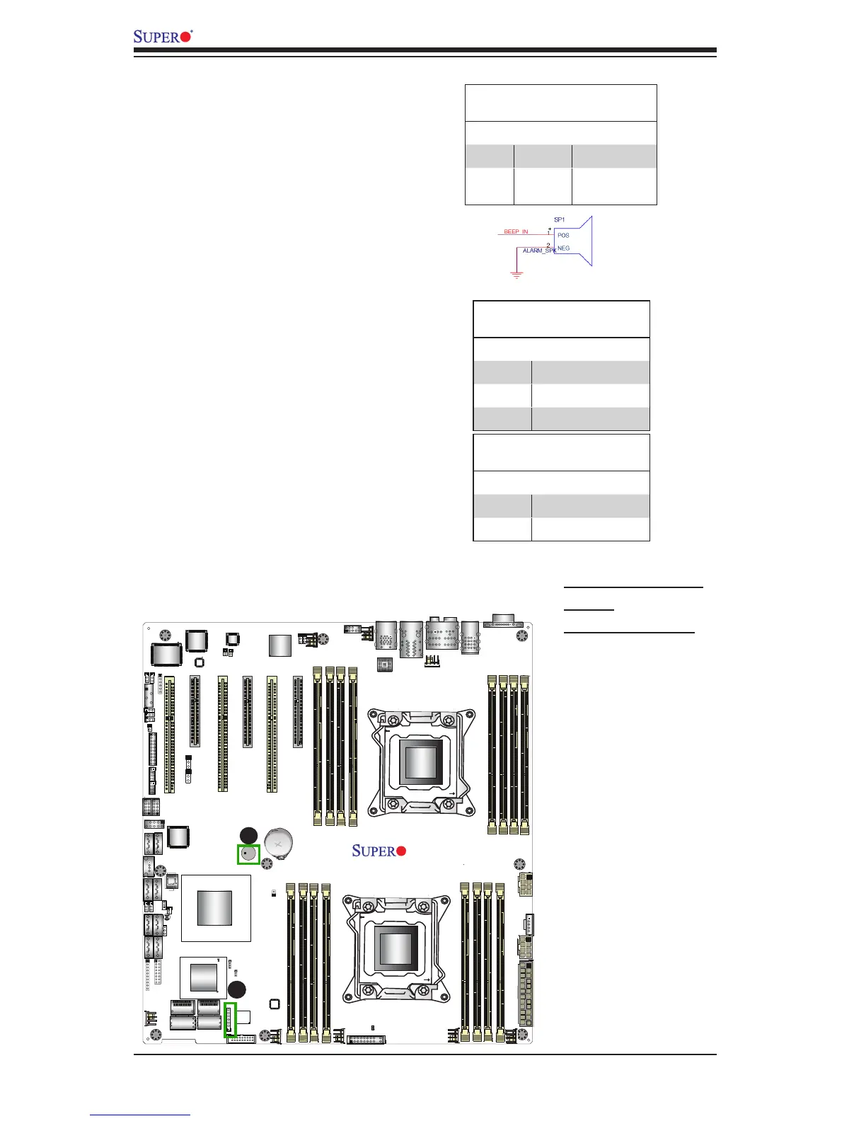
A. Internal Speaker
(Buzzer)
B. PWR LED/Speaker
Power LED/Speaker
On JD1 header, pins 1-3 are used for
power LED indication, and pins 4-7
are for the speaker. See the tables
on the right for pin denitions. Please
note that the speaker connector
pins (4-7) are used with an external
speaker. If you wish to use the on-
board speaker, you should close pins
6-7 with a jumper.
Speaker Connector
Pin Settings
Pin Setting Denition
Pins 4-7 External Speaker
Pins 6-7 Internal Speaker
Internal Speaker
The Internal Speaker, located at SP1,
can be used to provide audible indica-
tions for various beep codes. See the
table on the right for pin denitions.
Refer to the layout below for the loca-
tions of the Internal Buzzer (SP1).
Internal Buzzer (SP1)
Pin Denition
Pin# Denitions
Pin 1 Pos. (+) Beep In
Pin 2 Neg. (-) Alarm
Speaker
PWR LED Connector
Pin Denitions
Pin Setting Denition
Pin 1 Anode (+)
Pin2 Cathode (-)
Pin3 NA
A
B