2-40
X9DA7/X9DAE Motherboard User's Manual
JPWR1
JPI2C1
LE1
JTPM1
FAN5
FAN7
FAN6
FAN2
FAN3
FAN1
J18
JSD1
SP1
J29
JBR1
JWD1
STBY1
JPI1
JL1
CPU1
P2 DIMMH2
P2 DIMMG2
P2 DIMMH1
P2 DIMMG1
P2 DIMME2
P2 DIMMF1
P2 DIMMF2
P1 DIMMA2
P1 DIMMA1
P1 DIMMB2
P1 DIMMB1
P1 DIMMD2
P1 DIMMD1
J25
CPU2 Slot5 PCI-E 3.0 x16
CPU1 Slot3 PCI-E 3.0 x16
CPU2 Slot2 PCI-E 3.0 x4 in x8
TPM/Port80
JF1
Always Populate DIMMxA First
CPU2
S-SATA3
I-SATA1
COM1
USB3.0 0/1
S-SATA0
P1 DIMMC2
P1 DIMMC1
JSPDIF_In
JBT1
JPME1
BIOS
JD1
LAN1/2
USB2.0
0/1/2/3
JPWR2
J22
Intel
C602
CPU2 Slot6 PCI-E 3.0 x8
J21
7.1 Audio
Audio
CTRL
GLAN
CTRL
CPLD
S I/O
JPL1
CPU2 Slot4 PCI-E 3.0 x8
Battery
USB3.0 2/3
1394a
CTRL
(CPU1Fan)
(CPU2 Fan)
JIPMB1
JSPDIF_Out
J30
JI2C1
X9DA7/E
Rev.
1.0
L-SAS0~3
Audio FP
SCU-SGPIO1
T-SGPIO1
CNF1
CNF2
L-SAS4~7
FANA
JI2C2
J23
S-SATA2
USB5/6
S-SATA1
I-SATA2
I-SATA3
I-SATA0
CTRL
SAS
CPU1 Slot1 PCI-E 3.0 x16
JOH1
JS6
JS7
DS1
JS5
JS4
FP CTRL
KB/Mouse
USB4
P2 DIMME1
FAN4
A
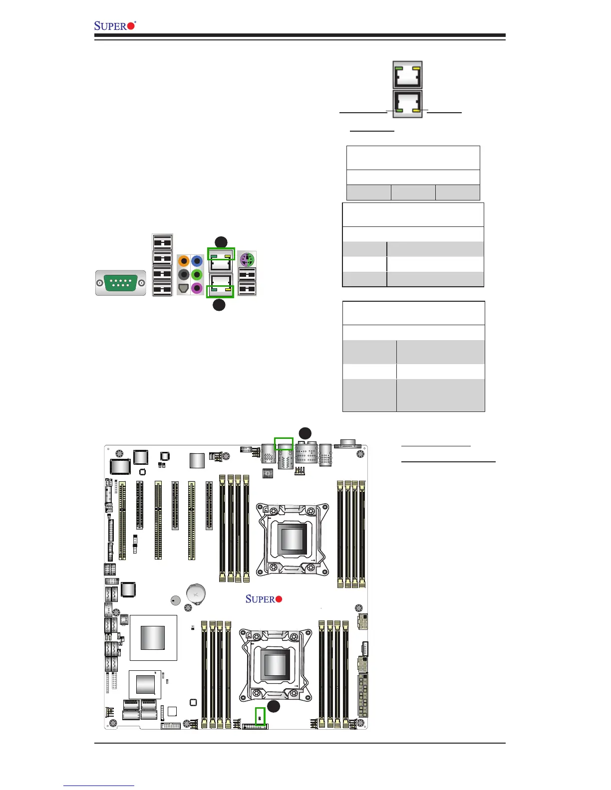
2-9 Onboard LED Indicators
A. LAN1/2 LEDs
B. Onboard PWR LED
B
A
Onboard Power LED
An Onboard Power LED is located at LE1
on the motherboard. When this LED is on,
the system is on. Be sure to turn off the
system and unplug the power cord before
removing or installing components. See
the tables at right for more information.
Onboard PWR LED Indicator (LE1)
LED Settings
LED Color Status
Off System Off (PWR cable
not connected)
Green System On
Green:
Flashing
Quickly
ACPI S1 State
GLAN LEDs
Two LAN ports (LAN 1/LAN 2) are located
on the IO Backplane of the motherboard.
Each Ethernet LAN port has two LEDs. The
green LED indicates activity, while the other
Link LED may be green, amber or off to
indicate the speed of the connections. See
the tables at right for more information.
LAN 1/LAN 2 Link LED
LED State
LED Color Denition
Off 10 Mbps or No Connection
Green 100 Mbps
Amber 1 Gbps
LAN 1/LAN 2 Activity LED
LED State
Color Status Denition
Green Flashing Active
Rear View (when facing the
rear side of the chassis)
Activity LED
Link LED
A

 Loading...


