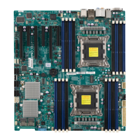
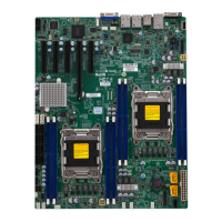
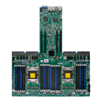
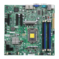
1-6
X9QR7-TF+/X9QRi-F+ Motherboard User’s Manual
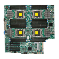
Note: To fully utilize all functionality and features offered by this quad
motherboard, be sure to install four CPUs on the motherboard. Without
four CPUs installed onboard, some functions or features might not be
supported.
Warning: To avoid damaging the power supply or motherboard, be sure to use a
power supply that contains a 24-pin and four 8-pin power connectors. Connect these
power supply connectors to the 24-pin power connector (JPW1) and the 8-pin power
connectors (JPW2~5) on the motherboard. Failure to do so will void the manufacturer
warranty on your power supply and motherboard.
(CPU4)Slot2/
(CPU1) Slot4
PCI-Express 3.0 x16 Slots
SWUID UID (Unit Identication) Switch
T-SGPIO1/2 Serial_Link General Purpose I/O Headers (JP4/JP5)
USB 0/1, 2/3 Back Panel USB 0/1, 2/3 Ports (JUSB0_1, JUSB2_3)
USB 4 Type A USB Connector (JUSB4) for Front Access
USB 5 Front Accessible USB Header
USB 6/7 Front Accessible USB Connections (JUSB6/7)
VGA Backpanel VGA Port
X9QR7-TF+/X9QRi-F+ LED Indicators
LED Description State Status
DS1 BMC Heartbeat LED Green BMC Normal
LEDUID1 Rear UID (Unit Identication) LED Blue Unit Identied
 Loading...
