Chapter 2: Installation
2-7
Chassis Intrusion
The Chassis Intrusion Detector is
located on JL1. See chapter one,
board layouts, and PC Health Moni-
tor page 1-14 for more information.
See Table 2-15 for pin definitions.
Pin
Number
1
2
Definition
Intrusion Input
Ground
Table 2-15
Chassis Intrusion
Detector Settings on
JL1
Open = Default, Close = Intrusion
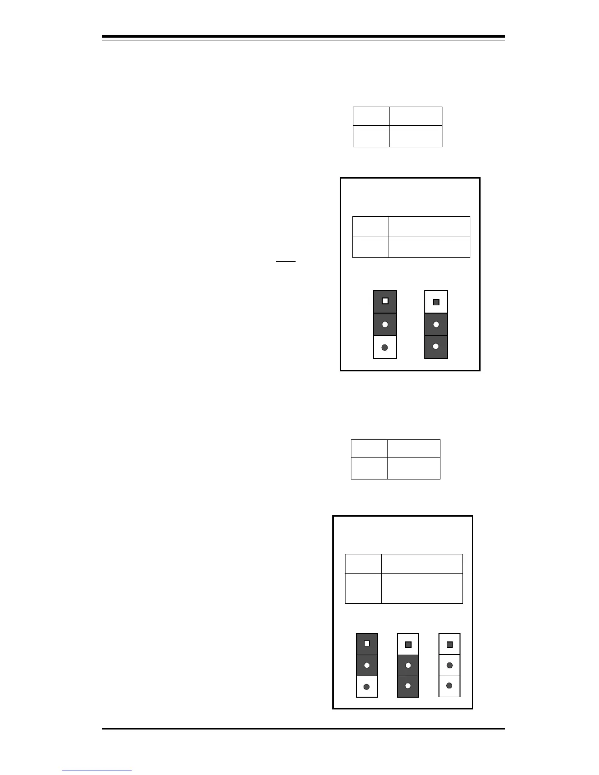
Keyboard Wake-Up
The Keyboard Wake-Up jumper is
located on JPWAKE. To enable
Keyboard Wake-UP, set the
JPWAKE jumper to 2-3 and
ENABLE the Keyboard Wake-Up
function in the system BIOS (see
page 5-18 for more details). Refer
to Table 2-16 for pin definitions.
Overheat LED
The Overheat LED connector is lo-
cated on pins 1 and 2 of JOH. Re-
fer to Table 2-17 for pin definitions.
Bus Speed
The Bus Speed jumper is located
on JP11. Note: Bus speed select
(JP11) is not available on the
370SLA and 370SLM using the
440 LX chipset. Refer to Table
2-18 for instructions on setting the
bus speed using jumper JP11.
JP11 jumper setting 1-2 is the
default setting.
(Note: Current
Celeron processors only support a
66 MHz bus speed. Future Celeron
processors may support a 100 MHz
bus speed.)
Table 2-16
Keyboard Wake-Up Pin
Definitions for JPWAKE
Jumper
Position
1-2
2-3
Definition
Disabled
Wake-Up Enabled
Position
1-2
Position
2-3
Disabled
Wake-Up Enabled
Table 2-18
Bus Speed Pin
Definitions for JP11
Jumper
Position
1-2
2-3
OFF
Definition
Auto Select
66 MHz
100 MHz
Position
1-2
Position
2-3
Auto Select
66 MHz
Position
OFF
100 MHz
Pin
Number
1
2
Definition
12V
OH Active
Table 2-17
Overheat LED Pin
Definition for JOH