Chapter 2: Installation
2-19
Power Button
OH/Fan Fail LED
1
NIC1 LED
Reset Button
2
Power Fail LED
HDD LED
Power LED
Reset
PWR
Vcc
Vcc
Vcc
Vcc/Front UID LED
Ground
Ground
1920
Vcc
X
Ground
NMI
X
Vcc
NIC2 LED
Power Fail LED
The Power Fail LED connection is
located on pins 5 and 6 of JF1. Re-
fer to the table on the right for pin
defi nitions.
PWR Fail LED
Pin Defi nitions (JF1)
Pin# Defi nition
5 Vcc
6 Ground
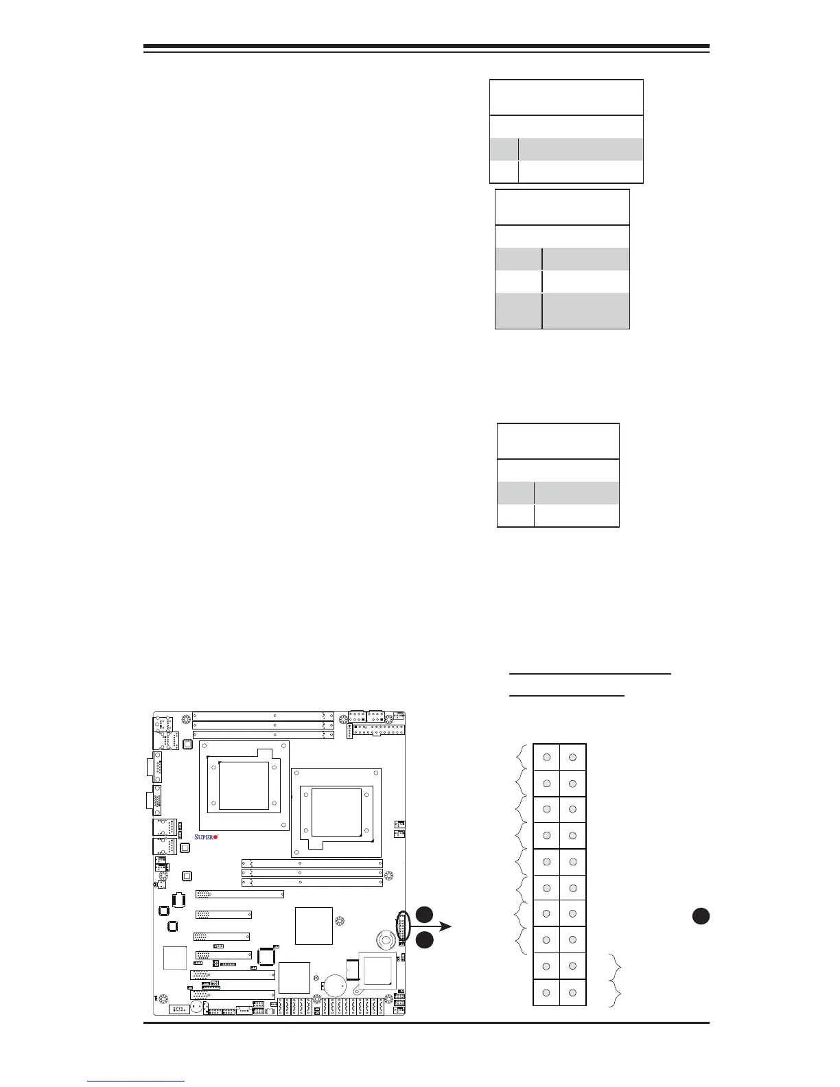
A
B
A. OH/Fan Fail & UID LEDs
B. PWR Supply Fail
X8DTL Series
Rev. 2.01
OH/Fan Fail LED
Pin Defi nitions (JF1)
Pin# Defi nition
7 Vcc/Front UID LED
8 OH/Fan Fail LED
OH/Fan Fail Indicator
Status
State Defi nition
Off Normal
On Overheat
Flash-
ing
Fan Fail
A
Overheat (OH)/Fan Fail/PWR Fail/
UID LED
Connect an LED cable to pins 7 and
8 of JF1 to use the Overheat/Fan
Fail/Power Fail and UID LED connec-
tions. The Red LED on pin 7 provides
warnings of an overheat, fan failure or
power failure. The Blue LED on pin
8 works as the front panel UID LED
indicator. The Red LED takes prece-
dence over the Blue LED by default.
Refer to the table on the right for pin
defi nitions.
 Loading...