2-36
X10SRi-F User’s Manual
DESIGNED IN USA
1.01REV:
X10SRi-F
JP3
JTPM1
JF1
JD1
J23
T-SGPIO1
T-SGPIO2
T-SGPIO3
JOH1
JL1
JPME2
JWD1
JPG1
JPB1
1
JI2C2
JI2C1
JBR1
JVRM2
JVRM1
JPL1
JSD1
JSD2
JIPMB1
JPWR1
JUIDB1
LE1
LE2
LEDM1
JBT1
BT1
FAN4
FAN1
FAN2
FAN3
FANA
FAN5
J24
JPI2C1
JSTBY1
S-SATA3
I-SATA4
I-SATA0
I-SATA1
I-SATA2
I-SATA3
S-SATA0
S-SATA1
S-SATA2
I-SATA5
SP1
1-2:ENABLE
2-3:DISABLE
JPB1:BMC
CPU
CPU SLOT5 PCI-E 3.0 X4(IN X8)
CPU SLOT4 PCI-E 3.0 X8
CPU SLOT3 PCI-E 3.0 X8
JPME2
2-3:ME MANUFACTURUNG MODE
1-2:Normal
USB0/1
DIMMC2
PWR LED1-3:
JD1:
SPEAKER4-7:
JBR1
1-2:Normal
2-3:BIOS recovery
:TPM/PRO80
USB8/9
USB6/7
LED
NMI
PWR
X
USB2/3
(3.0)
HDD
NIC
1
JWD1:Watch Dog
1-2:RST
2-3:NMI
LAN1
DIMMA2
DIMMA1
USB10(3.0)
FF
2
NIC
OH
LAN2
RST
PWR
PWR
FAIL
USB4/5
ON
1-2:ENABLE
2-3:DISABLE
JPG1:VGA
JI2C1/JI2C2
I2C bus for PCI-E slot
OFF:DISABLE
ON: ENABLE
PCH SLOT2 PCI-E 2.0 X4(IN X8)
PCH SLOT1 PCI-E 2.0 X2(IN X8)
COM2
COM1
DIMMB2
DIMMB1
PWR I2C
DIMMD2
DIMMD1
DIMMC1
IPMI_LAN
UID
USB11(3.0)
0N: POWER FORCE ON
JPL1:LAN1/2
1-2:ENABLE
VGA
2-3:DISABLE
LGA2011-3
1
1
CPU SLOT6 PCI-E 3.0 X16
BAR CODE
IPMI CODE
MAC CODE
BIOS
LICENSE
BIOS
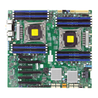
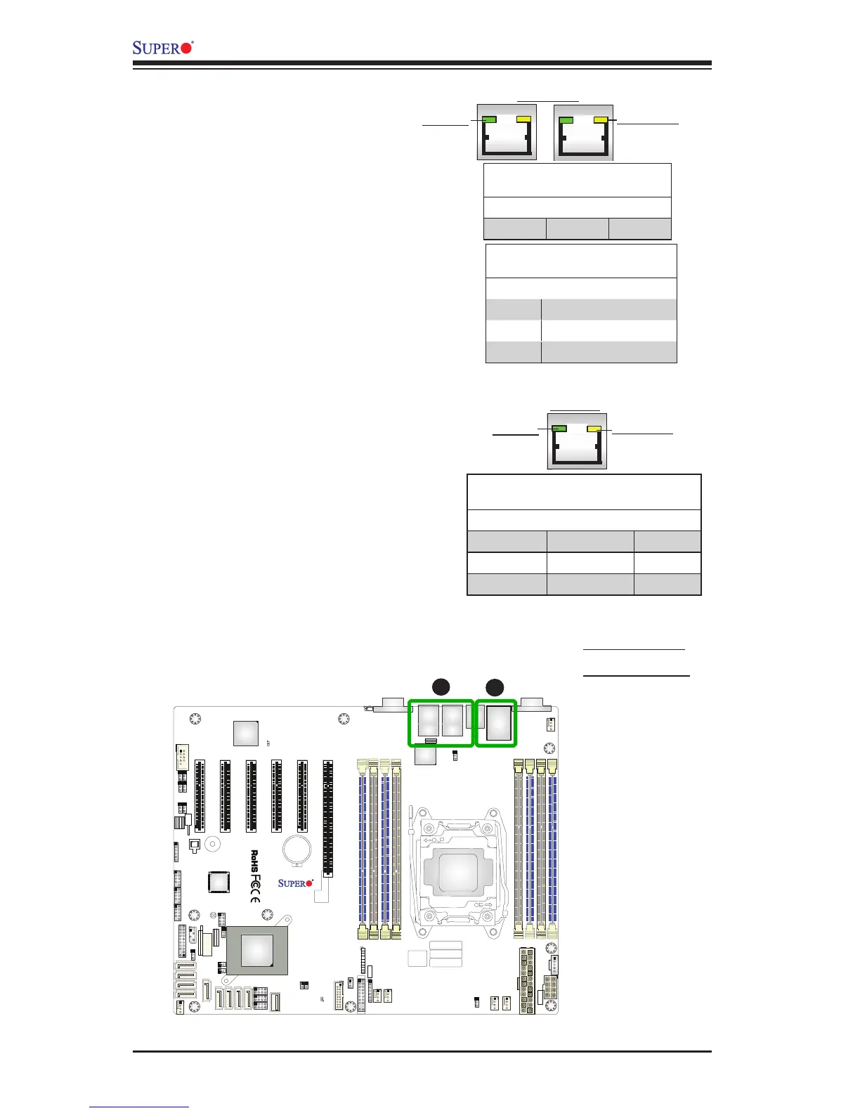
A. LAN 1/2 LEDs
B. IPMI_LAN LED
B
LAN 1/LAN 2 LEDs
Two LAN ports (LAN 1/LAN 2) are located
on the I/O backplane of the motherboard.
Each Ethernet LAN port has two LEDs.
The yellow LED indicates activity, while the
Link LED may be green, amber, or off to
indicate the speed of the connections. See
the tables on the right for more information.
2-9 Onboard Indicators
GLAN Ports 1/2 Link Indicator
LED Settings
LED Color Denition
Off No Connection/10 Mbps/
Green 100 Mbps
Amber 1 Gbps
GLAN 1/2 Activity Indicator
LED Settings
Color Status Denition
Yellow Flashing Active
IPMI Dedicated LAN LEDs
In addition to the Gigabit Ethernet ports,
an IPMI Dedicated LAN is also located
above the Backplane USB ports 2/3 on the
motherboard. The yellow LED on the right
indicates activity, while the green/amber
LED on the left indicates the speed of the
connection. See the table on the right for
more information.
Link LED
Activity LED
IPMI LAN
IPMI LAN Link LED (Left) &
Activity LED (Right)
Color/State Denition
Link (Left) Amber: Solid 1 Gbps
Green: Solid 100 Mbps
Activity (Right) Yellow: Blinking Active
Link LED
Activity LED
LAN1/LAN2
A

 Loading...