1. Fiber Connector
Extends the workgroup distance up to 2,000 meters.(Option)
2. RJ-45 Ports
Uses these twenty-four ports to connect to another Switches or Hubs. Each port
uses auto-negotiation for automatic speed and mode selection.
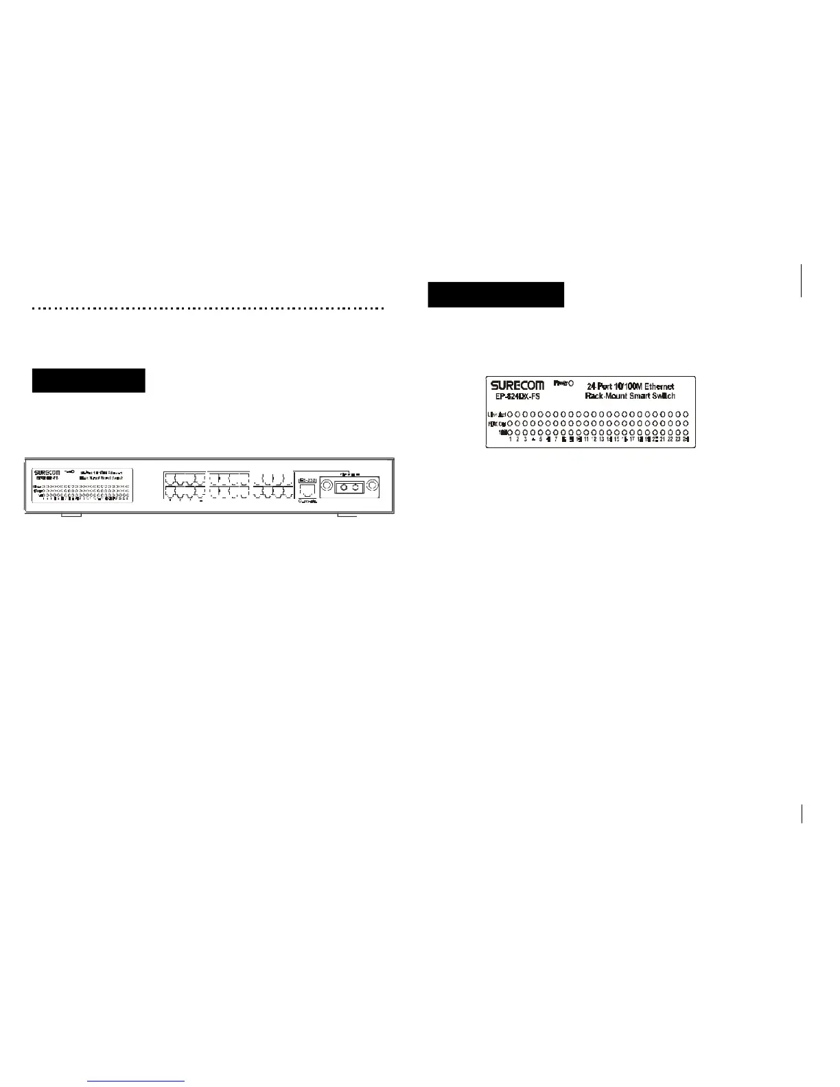
The front panel of the Switch consists of 24 (100/10Mbps Auto MDI/ MDI-X) ports.
2. Hardware
This chapter describes the front panel, LED indicators, and rear panel on the Switch.
2-2
The LED indicators are all located on the front panel which include one Power, one
Fiber Slide-in, one Link/Act., one FDX/Col,and one 100 indicator per port.
1. Power
The LED lights when the Switch is powered on. If the LED , fails to light, check
the AC power connector to ensure proper insertion of the power cord and that
the power switch is turned ON.
2. Link/Act.
These LEDs light up green to indicate that a valid link is established. These LEDs
flash whenever data packets are transmitting or receiving.
3. FDX/Col
These LEDs light up green to show the ports are operating in full-duplex (FDX)
mode. These LEDs flash whenever collision is detected on the network segments.
4. 100
These LEDs light when the ports run at 100Mbps. These LEDs are OFF when they
run at 10Mbps or are not connected.
LED Indicators
2-1
Front Panel
5 6 7 8 9 10 11 12
13 14 15 16 17
18 19 20 21 22 23 (24)
EP-824DX-FS
 Loading...