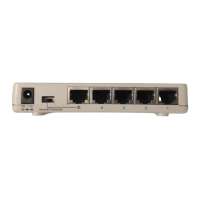
The rear panel consists of an AC power socket, a power switch, and a console port.
Rear Panel
1. Power Socket
Plugs the power cord into this socket.
2-32-
CHAPTER 3
Network DIY
This chapter describes how to connect this Switch to your Fast Ethernet network.
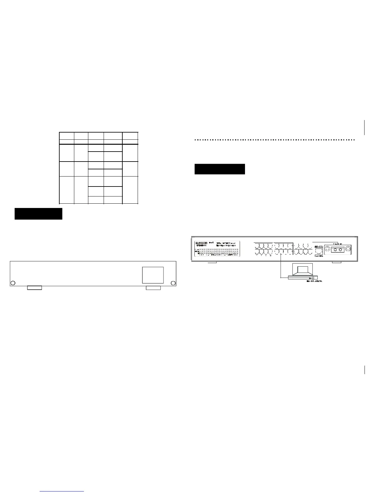
3. Network Connections
Make sure you have installed a 10BASE-T or 100BASE-TX network interface card for
connecting a PC to the Switch’s RJ-45 (MDI-X) station ports. If LEDs don’t light after
powering on the Switch, check if the LAN card, the cable and connectors are properly
attached to the PC and the Switch.
When a attached PC is powered on or reset:
1. The Link/Act LED will light
2. The FDX/Col LED depends on the installed LAN card’s capabilities for the PC
and the Switch connection.
3. The 100M LED will light for 100Mbps connection, otherwise it will be unlighted.
2-3 3-1
Switch to PC
You can connect any RJ-45 station port on the Switch to a PC via twisted-pair cable
with RJ-45 plugs at both ends. Use Category 3, 4 or 5 cable for standard 10Mbps
Ethernet connections, or Category 5 cable for 100Mbps Fast Ethernet connections.
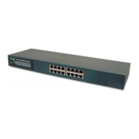
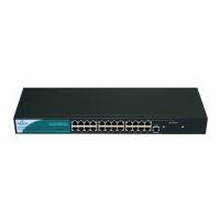
5 6 7 8 9 10 11 12
13 14 15 16 17
18 19 20 21 22 23 (24)
LED Color Status Descrition
Number of
LED
Power Green On Power on 1
Link/Act Green
On
Link status of
connected port
24(24 port)
Flashing
Data Transmi-
ssion status of
connected port
100 Green
On
100Mbps of
connected port
24(24 port)
Off
10Mbps of
connected port
FDX/Col Green
On
Full-Duplex
status of con-
nected port
24(24 port)
Off
Half-Duplex
status of con-
nected port
Flashing
Collision sta-tus
of conne-cted port
90~264VAC
47~63Hz
EP-824DX-FS
 Loading...