15
Rev: 03.10.20 lci1.com574-537-8900 CCD-0003622
INSTALLATION
OPTIONAL RF REMOTE CONTROL
STEP 2 WIRE RF RECEIVER
TOOLS REQUIRED:
1. None
PARTS REQUIRED:
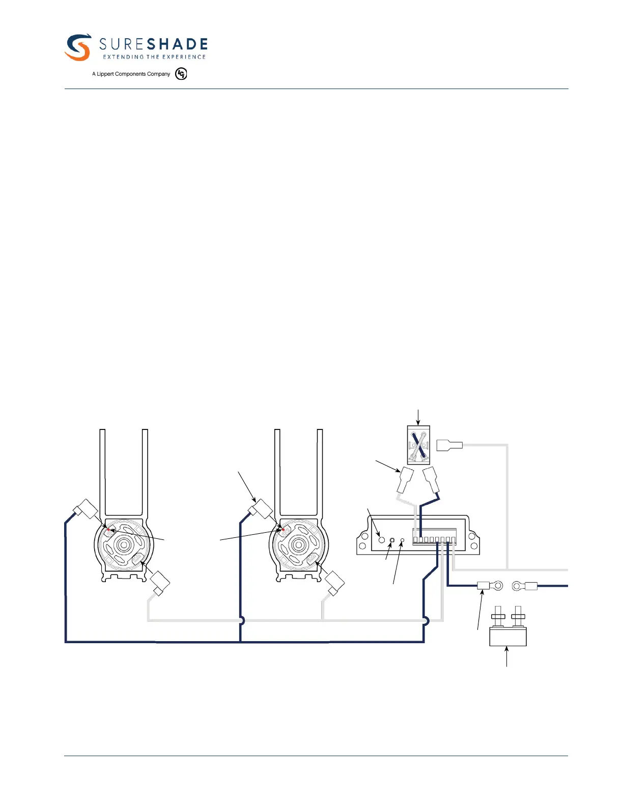
A. Actuator motors
B. RF receiver
C. 6 Amp short stop breaker
D. DPDT reversing toggle switch (if not previously installed)
E. 3/16" insulated ag spade terminal
F. 1/4" insulated spade terminal
G. #10 insulated ring terminal
Connect the battery and motor wires according to the schematic diagram shown. If a helm-mounted switch is
installed, connect it to the RF receiver as shown in the schematic.
NOTE RED DOT
ON OR NEAR
ONE MOTOR
TERMINAL
3/16" FLAG TERMINAL
FULLY INSULATED (4) REQ'D
DPDT REVERSING TOGGLE SWITCH
PHILMORE #30 - 125
BATTERY
POSITIVE (+)
1/4" SPADE TERMINAL
FULLY INSULATED
(3) REQUIRED
#10 INSULATED
RING TERMINAL
(2) REQUIRED
6 AMP SHORT STOP BREAKER
BUSSMAN #121A06-A2M-HD
NOTE: ALL WIRES TO BE 16 GAUGE
BATTERY
GROUND (-)
AUX BAT
STATUS
LIGHT
PROGRAM
BUTTON
OVERRIDE
SWITCH
 Loading...