
T
Tammy BakerJul 29, 2025
Why does my Suzuki Scooter battery run down quickly?
- CChristina Cooper PhDJul 29, 2025
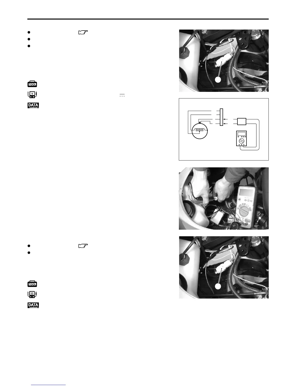
Your Suzuki Scooter's battery might be draining rapidly due to several reasons. It could be that accessories are using too much electricity, so check those first. There may also be current leaks; in this case, check the battery for current leakage. If there are no current leaks, measure the charging voltage between the battery terminals. Also, check the continuity of the starter coil. Finally, inspect the regulator/rectifier and the wires.


