EasyManuals Logo

Suzuki VLR1800 Service Manual

Suzuki VLR1800
624 pages
To Next Page IconTo Next Page
To Previous Page IconTo Previous Page
Page #461 background imageLoading...
Page #461 background image
Drive Chain / Drive Train / Drive Shaft: 3A-3
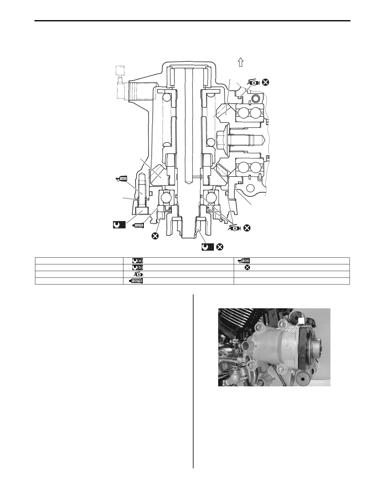
Secondary Gear Construction
B822H13106008
Secondary Driven Gear Assembly Removal and
Installation
B822H13106009
Removal
1) Remove the engine assembly. Refer to “Engine
Assembly Removal in Section 1D (Page 1D-18)”.
2) Remove the speed sensor. Refer to “Speed Sensor
Removal and Installation in Section 9C (Page 9C-
6)”.
3) Remove the secondary driven gear assembly (1).
1
2
3
4
(a)
(b)
FWD
I822H1310002-03
1. Shims : 95 Nm (9.5 kgf-m, 68.5 lb-ft) : Apply thread lock to the thread part.
2. Shims : 50 Nm (5.0 kgf-m, 36.0 lb-ft) : Do not reuse.
3. Secondary drive gear : Apply grease.
4. Secondary driven gear : Apply bond.
1
I822H1310003-01

Table of Contents

Questions and Answers:

Suzuki VLR1800 Specifications

General IconGeneral
ManufacturerSuzuki
ModelVLR1800
Compression Ratio10.5:1
Fuel SystemFuel injection
StarterElectric
Transmission5-speed
CategoryCruiser
Displacement1783 cc
IgnitionElectronic ignition (Transistorized)
Final DriveShaft
Front SuspensionTelescopic, coil spring, oil damped
Rear SuspensionLink type, coil spring, oil damped
Rear BrakesSingle disc
Ground Clearance140 mm
Seat Height705 mm

Related product manuals