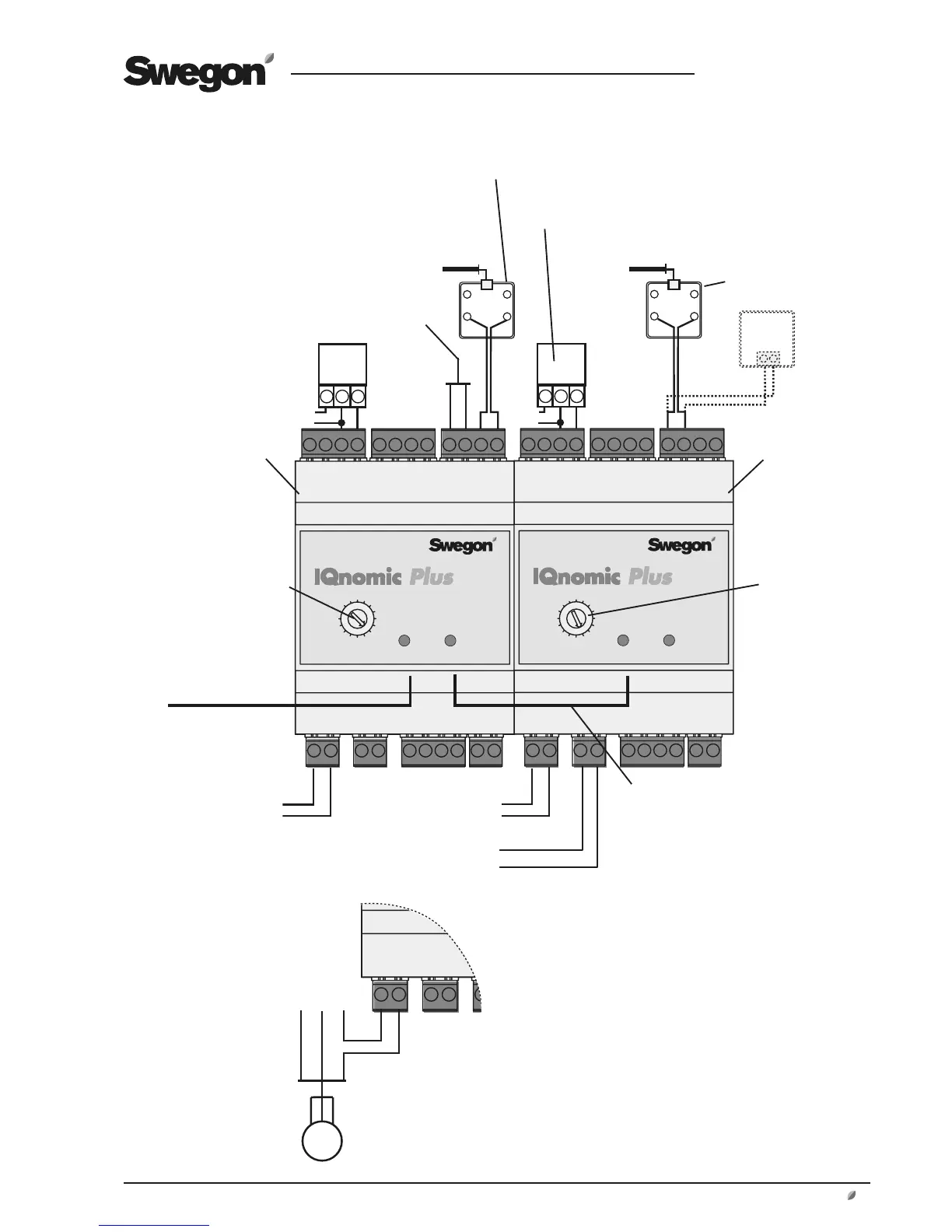
4. Electrical connections
IQnomic Plus module
Air heater for hot water
1)
Temp. sensor**
supply air
24 V AC*
Valve actuator, heating
G G0 Y
Freeze protection monitor sensor**
Control of pump
for heating
1)
Temp. sensor**
extract air/room
24 V AC*
Valve actuator, cooling
or air cooler 0-10 V
G G0 Y
Control of cooling step 1
or pump in cooling circuit
Control of cooling step 2
Brown
White
–
S
IQnomic Plus
module B
Communication cable to the
control unit of the air han-
dling unit, where it must be
connected to one of the con-
nections for Internal EIA-485.
Communication cable
between modules.
Function selector
switch in posi-
tion B
IQnomic Plus
module A
Function selector
switch in position A
* The 24 V AC power-
supply conductors can
be connected to Termi-
nals 60 (G) and 61 (G0)
in the control unit of
the air handling unit.
** Digital temperature
sensors require cor-
rect polarity. Be careful
when you wire the
conductors.
–
S
–
S
–
S
–
S
Room sensor
T1
GR
R1
RD
T1
GR
R1
RD
GNDData
Jack for wall mounting, 019611
Jack for wall moun-
ting, 019611
Pump controls
Supply voltage to 1-phase pump, max 1.5 A, can be obtained by wiring
to the following terminals inside the GOLD air handling unit:
Terminal 101 (L), terminal 102 (N).