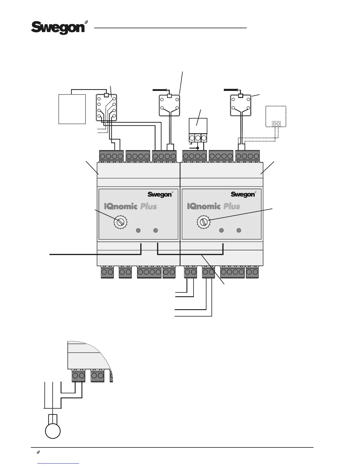
Temp. sensor,** extract air
24 VAC*
Valve actuator,
cooling or coo-
ling 0–10 V
G G0 Y
Control of cooling step 1
or pump in cooling circuit
Control of cooling step 2
Overheating
protection
–
S
IQnomic Plus
Module B
Communication cable to the
control unit of the air hand-
ling unit, where it should be
connected to one of the con-
nections for Internal EIA-485.
Communication cable bet-
ween modules.
Function selector
switch in Position B
IQnomic Plus
Module A
Function selector
switch in Position A
* The 24 V AC power-supply conductors can be
connected to Terminals 60 (G) and 61 (G0) in
the control unit of the air handling unit.
** Digital temperature sensors require correct
polarity. Be careful when you wire the conduc-
tors.
*** Electrical air heater above 36 kW 440 V
and above 27 kW 230 V (Norway) demand
supply voltage 24 VAC to internal control equip-
ment. Supply voltage 24 VAC can be connected
on the AHU control unit, terminal block 60 (G)
and 61 (G0).
–
S
–
S
–
S
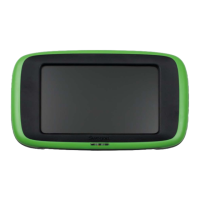
Room sensor
T1
GR
R1
RD
T1
GR
R1
RD
GNDData
Jack for wall mounting, 019611
Jack för väggmon-
tage, 019611
Jack for wall moun-
ting, 8-pole
BL
OR
BK
RD
WH
BR
YL
GR
24 VAC***
Pump controls
Supply voltage to 1-phase pump, max 1.5 A,
can be obtained by wiring to the following
terminals inside the GOLD air handling unit:
Terminal 101 (L), terminal 102 (N).