41
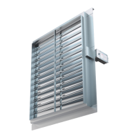
FIRE DAMPER - FD
PRODUCT OVERVIEW
DIMENSIONS
INSTALLATIONS
ACTUATORS
ACCESSORIES
REPLACEMENTS
MAINTENANCE AND OPERATION
Possible damper orientations
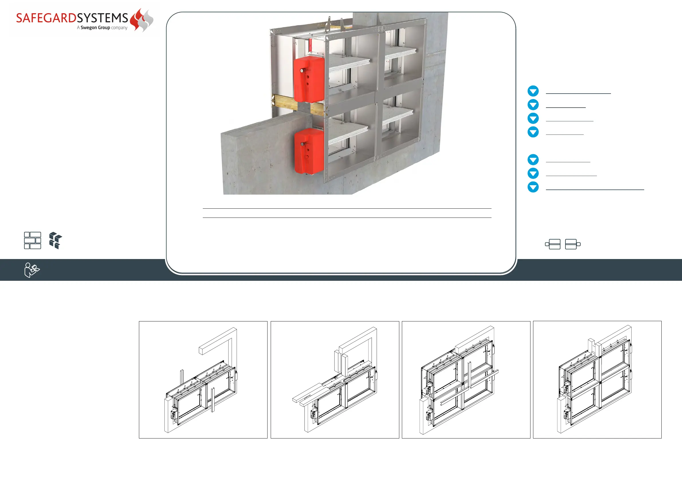
Battery assembly
installation
2x2
The wall is composed of concrete blocks
(minimum density of 550 kg/m³) or
reinforced concrete (minimum density of 2200 kg/m³)
and with a minimum thickness of 100 mm.
2
1
43
1. Prepare a hole of dimensions
2B + Connecting frame width (CF60/
CF100) + 80 mm and 2H + Connecting
frame width (CF60/CF100) + 80 mm.
Fill the bottom with mortar/gypsum in 50
mm height.
2. Place two lower dampers in the opening,
and fix dampers to the wall using screws
(only 2 sides facing aerated concrete).
Place the vertical part from the installation
kit to the dampers on both sides, and
attach it using the self-tapping screws.
Damper blade must be closed during
installation!
3. Fill the space between the dampers and
the wall with mortar/gypsum, and fill the
space between the dampers with mineral
wool (100 kg/m³ of density or higher).
Place two upper dampers and fix the
dampers to the wall using the screws (only
2 sides facing aerated concrete).
4. Place the vertical part and two horizontal parts from the installation kit to the dampers on both sides, and attach it using the self-tapping screws every
150 mm. Fill the gap between dampers and wall on upper side with mortar/gypsum and the installation is complete.
Test the operation of the damper blade!
Maximum dimension of fire dampers:
2X2 grid: 1500x800 mm
*For battery installation 2x2 use 8x connecting
frames and 2x connecting plate.
Installation only possible with FD40!
(1) Accessories (2) Type (3) Length
FD-A - CF60 - 800
(1)
(2)
Fire damper accessories
FD-A
Type
CF60 - Connecting frame 60 mm
CF100 - Connecting frame 100 mm
CP60- Connecting plate 60 mm
CP100- Connecting plate 100 mm
(3) Connecting frame length
200 ... 1500 [mm]
INSTALLATION
Always ensure the damper is sufficiently supported
 Loading...