ELECTRONIC START SYSTEM / E-GUN & StartTime V
Version 1.2 3481.560.02 Page 19
4 ELECTRICAL PROPERTIES
4.1 Power supply
Use only the original charger supplied by . If you do not use the original charger, it may destroy the
battery, cause damage to the unit, and possibly cause personal injury due to fire or/and electrical shock.
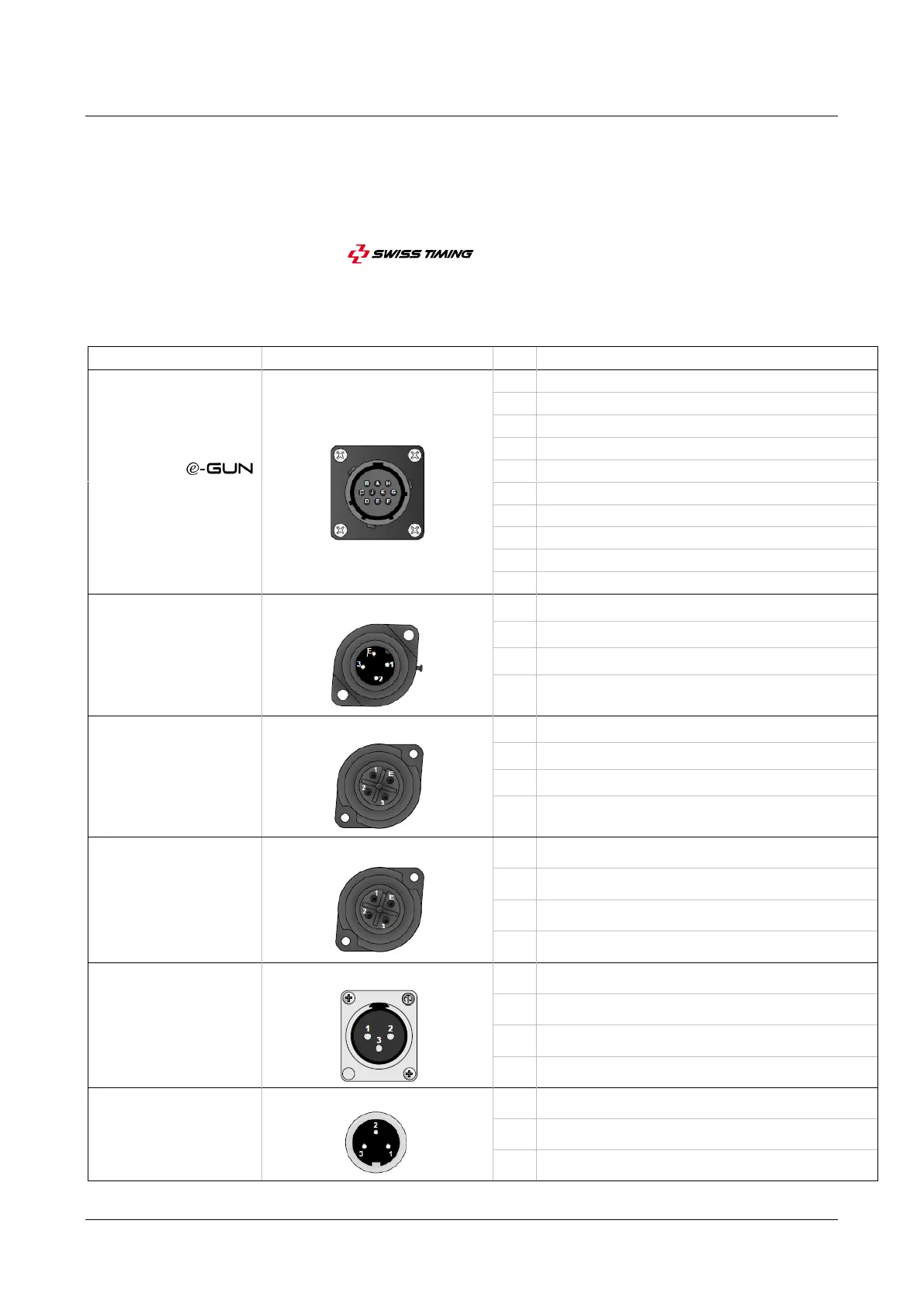
4.2 Connectors pinning
Connector type (Front view)
E-GUN / MICRO
This input allows the
connection of the
or Start & Microphone unit
(SMU). The StartTime V
detects automatically which
device is connected.
Control signal of the flash positive side
Control signal of the flash negative side
START
This connector is used to
transmit the start pulse or to
receive the ready signal.
Ready input, negative side
Start output, positive side
Start output, negative side
Ready input, positive side
FLASH
This output can be used to
control an external flash. The
connector is divided in two
parts, a power supply and a
control signal.
Power supply output (+12VDC)
Control signal of the external flash positive side
Control signal of the external flash negative side
SPEAKER
This connector is used to
transmit the sound signal to
an external speaker. The
connector is divided in two
channels: channel left and
right. Each channel has a RMS
power of 20W.
Left output of the speaker positive side
Left output of the speaker negative side
Right output of the speaker positive side
Right output of the speaker negative side
LINE OUT
This XLR connector is used to
transmit the sound signal to
an external sound system. The
external sound system must
have a typical impedance of
10k
.
GND (Shield connection, not shown on the figure)
CHARGER
This input is used to connect a
battery charger. The internal
battery is a 12V lead battery,
7Ah.
Positive terminal of the charger