1-7-1 T5307EA
ELECTRICAL ADJUSTMENT INSTRUCTIONS
General Note:
"CBA" is abbreviation for "Circuit Board
Assembly."
NOTE:
Electrical adjustments are required after replacing
circuit components and certain mechanical parts.
It is important to perform these adjustments only
after all repairs and replacements have been com-
pleted.
Also, do not attempt these adjustments unless the
proper equipment is available.
Test Equipment Required
1. NTSC Pattern Generator (Color Bar W/White Win-
dow, Red Color, Dot Pattern, Gray Scale, Mono-
scope, Multi-Burst)
2. AC Milli Voltmeter (RMS)
3. Alignment Tape (FL8A, FL8N), Blank Tape
4. DC Voltmeter
5. Oscilloscope: Dual-trace with 10:1 probe,
V-Range: 0.001~50V/Div,
F-Range: DC~AC-60MHz
6. Frequency Counter
7. Plastic Tip Driver
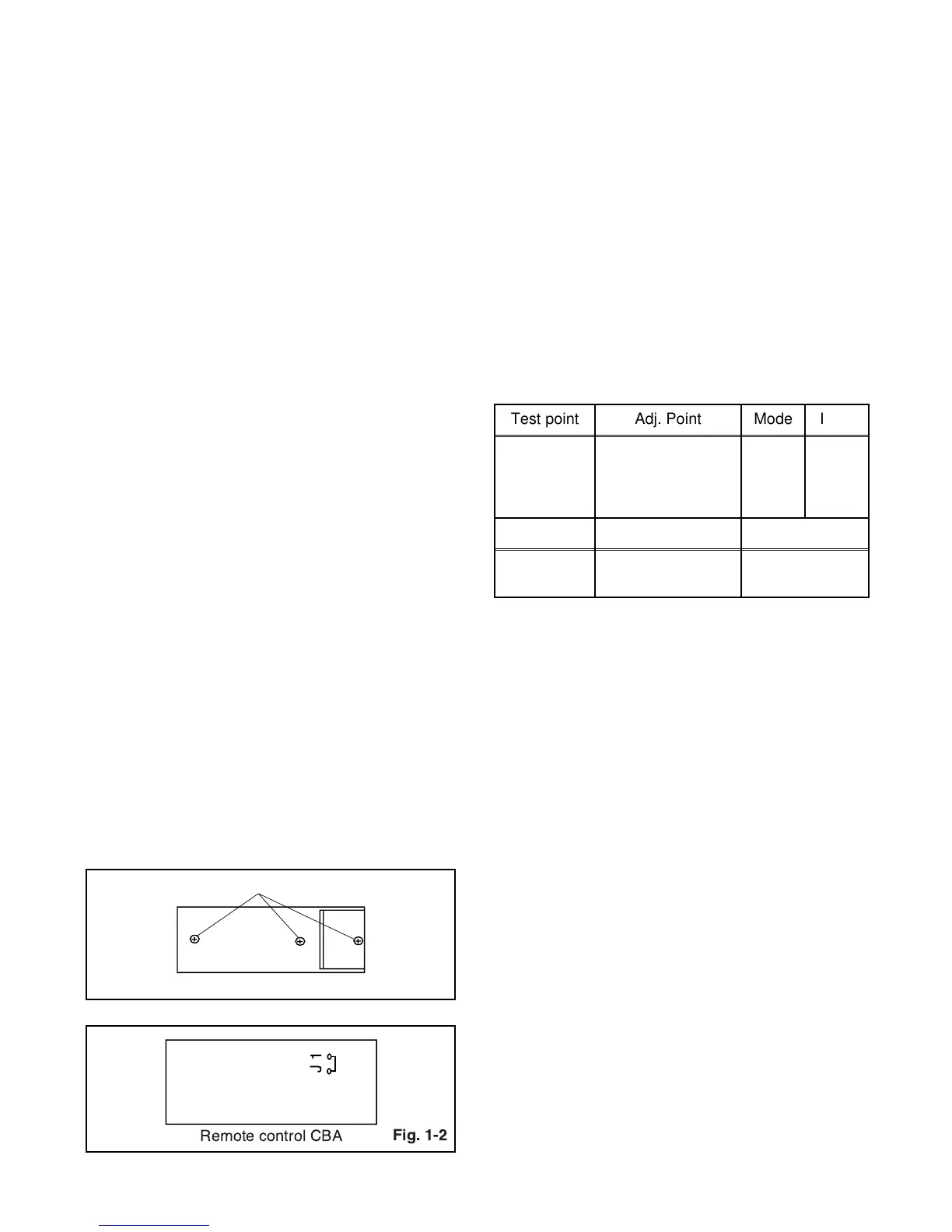
How to make service remote control
unit:
1. Prepare normal remote control unit. (Part No.
N0107UD) Remove 3 screws from the back lid.
(Fig. 1-1)
2. Add J1 (Jumper Wire) to the remote control CBA.
(Fig. 1-2)
How to Set up the Service mode:
Service Mode:
1. Use the service remote control unit.
2. Turn the power on.
3. Press " WAKE-UP/SLEEP " button on the service
remote control unit.
1. DC 105V (+B) Adjustment
[ SRC2213/SRC22134 ]
Purpose: To obtain correct operation.
Symptom of Misadjustment: The picture is dark and
unit does not operate correctly.
Note: J192(+B), J213(GND), VR601 --- Main CBA
1. Connect the unit to AC Power Outlet.
2. Connect DC Volt Meter to J192(+B) and
J213(GND).
3. Adjust VR601 so that the voltage of J192(+B)
becomes +105±0.5V DC.
SCREW
Fig. 1-1
Remote control unit (Bottom)
J1
Remote control CBA
Test point Adj. Point Mode Input
J192
(+B)
J213
(GND)
VR601 --- -----
Tape M. EQ. Spec.
---
DC Voltmeter
Plastic Tip Driver
+105±0.5V DC