technical reference
322
Synrad Firestar f-Series operator’s manual
User I/O connections
Sample outputs
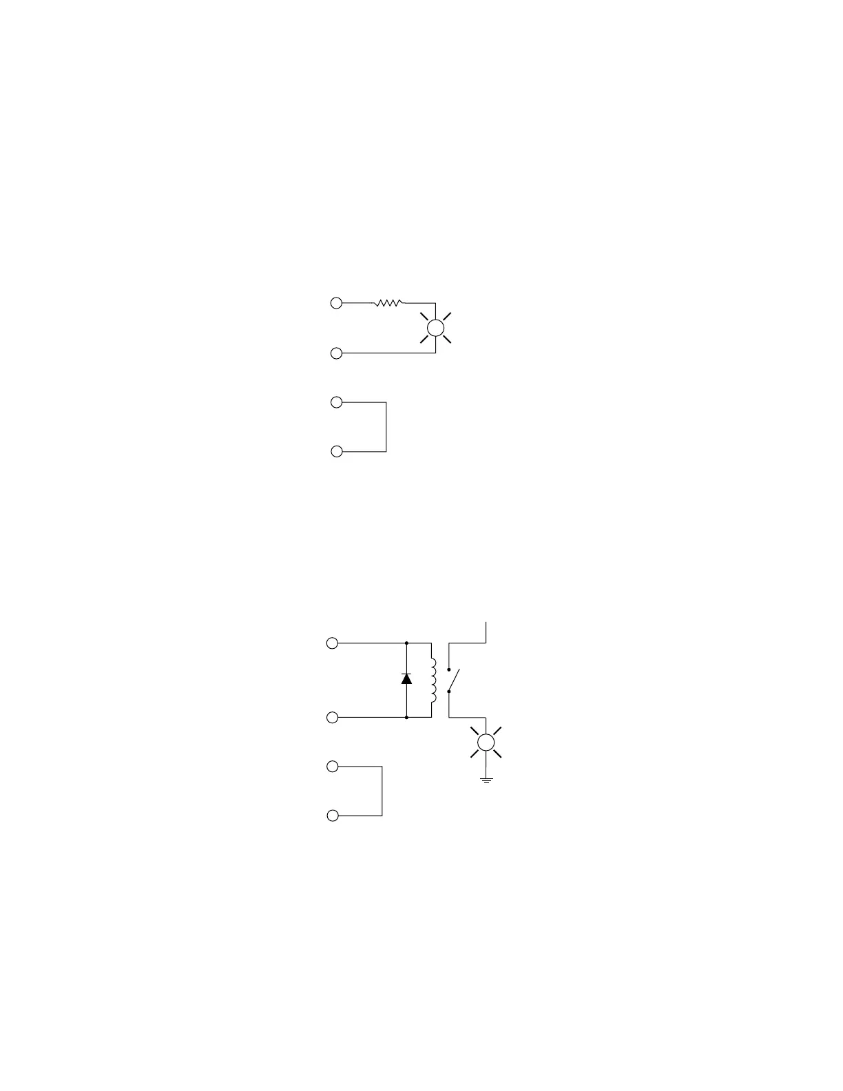
Firestar’s optoisolated, bi-directional switched outputs can drive small loads (50 mA max), PLC inputs,
or relays that can control higher current loads. Figure 3-14 illustrates one method of controlling a remote
warning lamp using power supplied by Firestar’s +24 VDC Auxiliary Power output. Remember to size
current-limiting resistor, R1, so that the current draw does not exceed 50 mA.
+24 VDC AUXILIARY
WER
LASER ACTIVE
AUX. DC POWER
OUND
L
R1
Figure 3-14 Firestar output driving warning lamp
Figure 3-15 illustrates a method for controlling a higher voltage, higher current load by using a 24V con-
trol relay. Ensure that the relay coil’s pull-in current does not exceed 50 mA. A diode or surge suppressor
must be installed across the relay coil to prevent voltage spikes from damaging Firestar outputs.
+24 VDC AUXILIARY
WER
LASER ACTIVE
AUX.DC POWER
OUND
L
Figure 3-15 Firestar output driving relay
 Loading...

