operation
31
SYNRAD OEM v30 Operator’s Manual Version 2
Controls and indicators
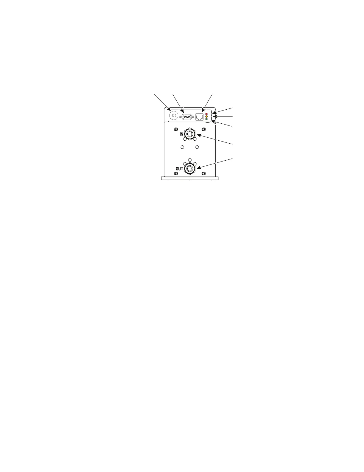
OEM v30 rear panel
Figure 3-2 OEM v30 rear panel controls and indicators
4
DC Power Cables – receives +30 VDC from the DC power supply. The DC power cables are manu-
factured from #12 AWG wire and measure 1 meter (40 inches) in length. The red (positive) cable
contains a replaceable in-line fuse. If fuse replacement is required, replace it with a Cooper Buss-
mann ABC-20-R, a Littelfuse 314020 or equivalent 20 A, fast-blow fuse.
5
Interface A (DB-9) Connector – provides a connection point for auxiliary output power as well as
input and output signals. See Interface connections in the Technical Reference chapter for DB-9 inter-
face details and pinouts.
6
Interface B (RJ45) Connector – provides a connection point for auxiliary output power as well as
input and output signals. See Interface connections in the Technical Reference chapter for RJ45 inter-
face details and pinouts.
7
LASE Indicator – illuminates red to indicate that the laser is actively lasing. The LASE indicator is
o when tickle pulses are being generated and illuminates red when PWM Command signal pulses
are long enough to produce laser output.
8
RDY (Ready) Indicator – illuminates yellow when the laser is enabled, indicating that lasing will
begin when a PWM Command signal is applied.
9
PWR (Power) Indicator – illuminates green when +30 VDC power is applied to the laser.
10
WATER IN Port (water-cooled models only) – labeled IN, this connection provides the cooling
water inlet to the v30’s coolant path.
11
WATER OUT Port (water-cooled models only) – labeled OUT, this connection provides the cooling
water outlet from the v30’s coolant path.
8
9
INTERFACE
LASE
RDY
PWR
AB
7
10
11
(Water-Cooled v30 Shown)