operation
30
SYNRAD OEM v30 Operator’s Manual Version 2
Controls and indicators
The Controls and indicators section includes subsections:
■ OEM v30 front panel
■ OEM v30 rear panel
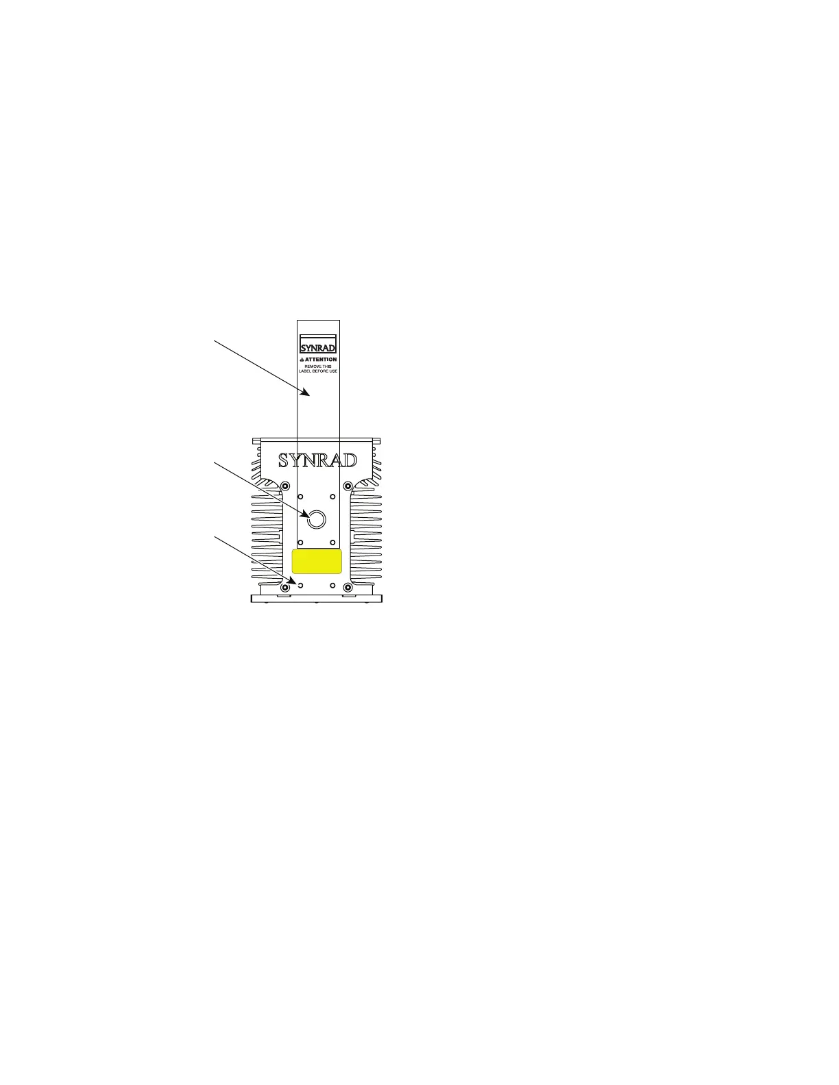
OEM v30 front panel
Figure 3-1 OEM v30 front panel controls and indicators
1
Aperture Seal – prevents dust from damaging the output coupler during shipping. Remove the red
self-adhesive seal before applying power to the laser!
2
Laser Aperture – provides an opening in the OEM v30’s front panel from which the beam exits.
3
Optical Accessories Mounting – provides six threaded holes (8–32 UNC) for mounting optional
beam delivery components Because excessive weight may damage the laser, consult SYNRAD before
mounting components not specically designed as Firestar options. Refer to OEM v30 package outline
drawings in the Technical Reference chapter for mounting hole dimensions.
Note: When mounting optical components to the OEM v30 laser, excessive fastener length may damage
the laser. See the appropriate package outline drawing for important information about accessory
mounting hole depth.
2
1
AVOID EXPOSURE
Invisible laser radiation
is emitted from
this aperture.