technical reference
40
SYNRAD OEM v30 Operator’s Manual Version 2
Controlling laser power
Warning
serious
personal
injury
Always use shielded cable when connecting your PWM Command
signal source to PWM Positive/PWM Negative inputs. In electrical-
ly-noisy environments, long lengths of unshielded wire act like an
antenna and may generate enough voltage to trigger uncommanded
lasing.
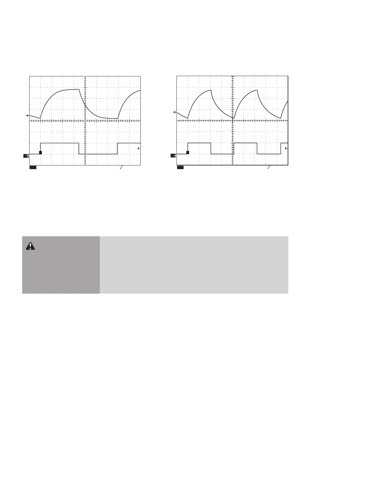
Figure 4-2 Representative OEM v30 waveforms
Command signal
1
5.00 V M 50.0µs Ch1 1.24
Ch1
Ty pical optical output pulse (50% duty cycle at 3 kHz)
T
2
1
5.00 V M 50.0µs Ch1 1.24
Ch1
Ty pical optical output pulse (50% duty cycle at 5 kHz)
T
2
The modulated Command signal applied between Pin 1, PWM Positive, and Pin 6, PWM Negative, on
either interface connector has three basic parameters: signal amplitude, base frequency, and PWM duty
cycle. By changing these parameters, you can command the beam to perform a variety of marking, cutting,
welding, or drilling operations.
The rst Command signal parameter, signal amplitude, is a square wave that is either logic low—corre-
sponding to laser beam o, or logic high—corresponding to beam on. The laser o voltage, typically 0 V,
can range from 0.0 V to +0.8 VDC while the laser on voltage, typically 5 V, can range from +3.5 V to +6.7
VDC.
Base frequency, the second parameter, is the repetition rate of the PWM input signal. The standard base
frequency is 5 kHz, which has a period of 200 µs. Maximum PWM frequency is 100 kHz.
The third Command signal parameter, PWM duty cycle, is the percentage of the period that the Com-
mand signal is high. If the Command signal’s amplitude (at 5 kHz) is high for 100 µs and low for 100 µs,
it has a 50% duty cycle; if the amplitude is high for 190 µs and low for 10 µs, it has a 95% duty cycle. The
following gure illustrates PWM Command signal parameters while the following table lists PWM signal
specications.

 Loading...
